diy solar

diy solar

JBD-SP044S060 on my garden off grid setup

Jockmacrea

New Member
Joined
Jan 6, 2022
Messages
23
Hi, I’m located in the Scottish Borders near the town of Hawick,
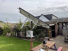
just finished my garden solar setup comprising
1x440 mono crystalline 42v 10.5Amp panel
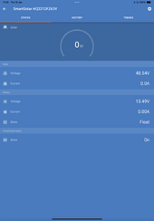
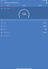
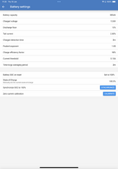
1xVictron smart shunt
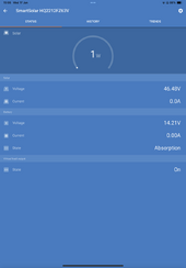
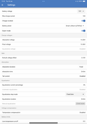
1 x Victron 100/50 MPPT controller
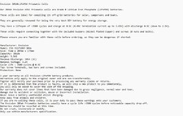
4x300Ah 3.2v Grade B lifepo4 cells
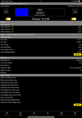
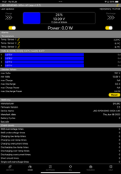
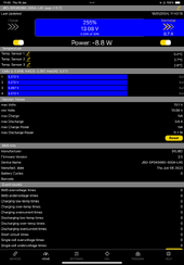
1xJBD-SP04S060 BMS
1x4K/8K 12Vdc to 240Ac inverter
Various switches and fuses.

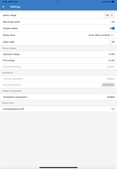
Ok lots of people tell me I got it all wrong and should have opted for a 24V system. With 24V this would have kept voltage drops to a minimum and reduce the size of the cables used. Well the max length of my cables are no longer than 12” and i used gauge 0 Cable. Hopefully this will be fine. Too late for me to change now, I cannot afford to purchase another 4 cells. I will however for one more 440W panel to my setup. So for now, I have made my bed and will lay in it. So with all that said the big switch on came today, all went well and the smart shunt was updated and configured. I now need to pair the Bms Bluetooth so if someone can point me to thelink for download.

Please be aware the complete installation will be guarded with plexiglas to ensure max safety.
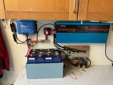
I’m a raw beginner so any comments whether good or bad would be most welcome. Attached is a picture showing my automated sunseeking array and my Battery/BMS installation.
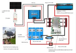
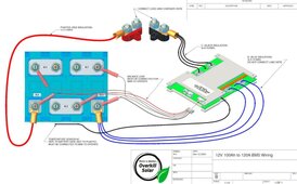
 

Attachments

  • IMG_0498.jpeg
    IMG_0498.jpeg
    278 KB · Views: 38
  • IMG_0378.jpeg
    IMG_0378.jpeg
    335.4 KB · Views: 38
Not a bad first attempt, but 4kW is truly a huge ask for 12V.

4000/.85/12.8 = 367A

Doubt any of your wiring is rated for that, but if you plan to run at much lower than peak power, you'll probably be fine.

Not a bad first attempt.
 
Not a bad first attempt, but 4kW is truly a huge ask for 12V.

4000/.85/12.8 = 367A

Doubt any of your wiring is rated for that, but if you plan to run at much lower than peak power, you'll probably be fine.

Not a bad first attempt.
Thanks for your reply, I doubt very much that I will be approaching anything near 367Amp.
 
Thanks for your reply, I doubt very much that I will be approaching anything near 367Amp.

You have cells capable of more than that and a 300A BMS, so your source is capable of very high output.

You also have a load that can draw more than the source. Not sure what your fuse it.

Doubt any of your wiring is rated for that, but if you plan to run at much lower than peak power, you'll probably be fine.

You need to make an assessment of your wiring and fuses and confirm where their limits are and have a hard number in your head, i.e., "I must never run more than X Watts, or I will exceed the ratings of <whatever the limiting component is>"

The double wire scheme at the positive terminal is generally a no-no, but I expect that they are what came with the inverter, so it makes sense to use them. What the Chinese supply with cheap inverters are notoriously undersized. For future reference, each conductor in a circuit should have suitable over-current protection, i.e., remove one of the wires and then see if the fuse/breaker is adequate to protect it.

On a side note, I'd be very interested to see what the production of that tracker is. Unfortunately, it would be pretty laborious to get that as you'd need to make sure the charger was in bulk mode the whole time by using more power than it can product.
 
You have cells capable of more than that and a 300A BMS, so your source is capable of very high output.

You also have a load that can draw more than the source. Not sure what your fuse it.


You need to make an assessment of your wiring and fuses and confirm where their limits are and have a hard number in your head, i.e., "I must never run more than X Watts, or I will exceed the ratings of <whatever the limiting component is>"

The double wire scheme at the positive terminal is generally a no-no, but I expect that they are what came with the inverter, so it makes sense to use them. What the Chinese supply with cheap inverters are notoriously undersized. For future reference, each conductor in a circuit should have suitable over-current protection, i.e., remove one of the wires and then see if the fuse/breaker is adequate to protect it.

On a side note, I'd be very interested to see what the production of that tracker is. Unfortunately, it would be pretty laborious to get that as you'd need to make sure the charger was in bulk mode the whole time by using more power than it can product.
Good advice, I'll swap those double wires out as you suggest. I connected the system up today and here's some snapshots of what I get using the Victron connect app and the Overkillsolar app. No go easy on me I'm 76 years old but willing to learn. I purchased my cells from Fogstar just over 2 months ago so they've been sitting a while. They show 3.277V for 3 of them and 3.271 for the other. Is this OK? Thanks for spending the time with me.
 

Attachments

  • No1.png
    No1.png
    73.3 KB · Views: 9
  • No2.png
    No2.png
    63.6 KB · Views: 8
  • Overkill.png
    Overkill.png
    153.9 KB · Views: 9
  • Cell Spec.jpg
    Cell Spec.jpg
    150 KB · Views: 10
Good advice, I'll swap those double wires out as you suggest. I connected the system up today and here's some snapshots of what I get using the Victron connect app and the Overkillsolar app. No go easy on me I'm 76 years old but willing to learn. I purchased my cells from Fogstar just over 2 months ago so they've been sitting a while. They show 3.277V for 3 of them and 3.271 for the other. Is this OK? Thanks for spending the time with me.

Everybody starts somewhere.

I just missed out on a really cheap sale on those same cells here in the states... they were in stock for maybe 1/2 day.

3.271-3.277 indicates these are at a very low state of charge. I would estimate about 30% - this is normal as these cells must ship at no higher than 30% SoC to comply with international hazmat regulations. This suggests that you did not top balance the cells prior to build. Not a huge deal, but just know that it is very likely you may experience difficulty attaining 14.2V without the BMS triggering protection due to one cell being above the cut-off.

Looks like your charging parameters are good. Please toggle the EXPERT switch on and provide screencap. The switch only controls what is displayed. The expert options are still in effect, and they can use some tweaking.

One setting in particular - low temp cut off of 5°C. In the absence of an external sensor, the MPPT uses its internal sensor to take a temperature reading when the unit wakes up with PV voltage detected. It then behaves as though its that temperature for the entire day, so if it happens to be below 5°C in the morning, you will not get charging all day. You have two options: 1) smartshunt temp sensor and 2) smart battery sense. #1 makes the most sense. Cheaper and a better value.

here is the VE.Smart networking resource you asked for (missed it the first time):


Your MPPT is showing 14.2V while your BMS is reading 13.1V. This implies the MPPT is not connected to the battery, or there is a GROSS error. Please measure your battery terminals with a voltmeter and the battery screw-down terminals on the MPPT with a separate voltmeter.

Lastly, longest life is attained via cell compression. Most cell datasheets recommend compression.

Please provide:
  1. MPPT settings with expert switch on.
  2. Smartshunt settings.
  3. BMS settings
  4. Voltmeter measurements:
    1. battery at terminals
    2. MPPT at screw-down battery terminals
    3. What VictronConnect reports for battery voltage
  5. What is your main fuse size between your inverter and bus bar?
  6. What gauge or mm^2 size are your cables for:
    1. MPPT to bus bar.
    2. MPPT to (-) shunt (-).
    3. Inverter to bus bar.
    4. Inverter Battery (-) to shunt
    5. BMS (-) wires.
 
Wow there does seem to be something amiss with the differences between the Battery terminal voltage and with that of what the mppt reports.
Batterey terminal is at 13.1V and Mppt is 13.48V the PV voltage is 46.63. I wtll get the other detais later meanwhile I'm of to the toothwright, hope he doesn't pull any. I have included my full schematic, I hope you can find an error. Also some more screen shots i gathered this morning. I will remove the cells and top balance as suggested. I had news this morning that Frogstar agree to swap my cells for the Grade A eve cells which is what I originally requested.
Many thanks . George
 

Attachments

  • 1801-6.png
    1801-6.png
    62.5 KB · Views: 19
  • Master screenshot.jpg
    Master screenshot.jpg
    151.7 KB · Views: 16
  • 1801-5.png
    1801-5.png
    61.9 KB · Views: 21
  • 1801-4.png
    1801-4.png
    73.5 KB · Views: 13
  • 1801-3.png
    1801-3.png
    159.4 KB · Views: 10
  • 1801-2.png
    1801-2.png
    102.6 KB · Views: 13
  • 1801-1.PNG
    1801-1.PNG
    164.3 KB · Views: 14
Wow there does seem to be something amiss with the differences between the Battery terminal voltage and with that of what the mppt reports.
Batterey terminal is at 13.1V and Mppt is 13.48V the PV voltage is 46.63. I wtll get the other detais later meanwhile I'm of to the toothwright, hope he doesn't pull any. I have included my full schematic, I hope you can find an error. Also some more screen shots i gathered this morning. I will remove the cells and top balance as suggested. I had news this morning that Frogstar agree to swap my cells for the Grade A eve cells which is what I originally requested.
Many thanks . George

To clarify, at roughly the same time please confirm:

  • Voltmeter measures 13.1V at battery terminals AND at MPPT battery terminals:
1705588849455.png
  • BMS measures 13.08V
  • MPPT measures 13.48V
  • Shunt measures 13.12V

If the above four are true, your MPPT is out of spec. There is a 1% max error permitted on voltage accuracy. You have two options:

1) return it to your reseller
2) create the VE.Smart network to override the MPPT voltage with the shunt voltage

Configuration changes:
MPPT:
  • Change fixed absorption time to 30 minutes.
  • You have a 10A output limit on the charger, so you'll never get more than ~140W out of the charger.
  • If there's actual risk of charging below 5°C, Consider disabling low temp protection unless you get a Victron temperature feeding the unit.
Shunt:
14.0 charged
tail current 5%
Battery SoC on reset to "Keep Soc" - your current setting will default to 100% if shunt power is lost, i.e., your empty battery could read 100%.

Still Need:
  • Your diagram shows a fuse between the MPPT and battery. I'm not seeing a fuse at that location. I see a fuse between the battery and inverter. What is the fuse between the battery and inverter?
  • I don't see your BMS settings. You've shown the home screen twice. Need the settings screen.
Something I just noticed. The battery disconnect is usually between the battery and the rest of the system to completely isolate the battery. Yours only disconnects the inverter from the battery.
 
To clarify, at roughly the same time please confirm:

  • Voltmeter measures 13.1V at battery terminals AND at MPPT battery terminals: Yes
View attachment 189693
  • BMS measures 13.08V
  • MPPT measures 13.48V
  • Shunt measures 13.12V All confirmed.

If the above four are true, your MPPT is out of spec. There is a 1% max error permitted on voltage accuracy. You have two options:

1) return it to your reseller
2) create the VE.Smart network to override the MPPT voltage with the shunt voltage

Configuration changes:
MPPT:
  • Change fixed absorption time to 30 minutes. DONE
  • You have a 10A output limit on the charger, so you'll never get more than ~140W out of the charger. Now 20Amp
  • If there's actual risk of charging below 5°C, Consider disabling low temp protection unless you get a Victron temperature feeding the unit.
Shunt:
14.0 charged DONE
tail current 5% DONE
Battery SoC on reset to "Keep Soc" - your current setting will default to 100% if shunt power is lost, i.e., your empty battery could read 100%. DONE

Still Need:
  • Your diagram shows a fuse between the MPPT and battery. I'm not seeing a fuse at that location. I see a fuse between the battery and inverter. What is the fuse between the battery and inverter? 300A DONE
  • I don't see your BMS settings. You've shown the home screen twice. Need the settings screen. Added
Something I just noticed. The battery disconnect is usually between the battery and the rest of the system to completely isolate the battery. Yours only disconnects the inverter from the battery. Please feel free to alter my schematic, I'd appreciate that.
I think I have made all the alterations you asked me for. And also included is the BMS Config screenshot.
I really hope I'm not being too much of a pain in the but. Big thanks.. George
 

Attachments

  • MMP advanced.png
    MMP advanced.png
    108.2 KB · Views: 2
  • BMS Config.png
    BMS Config.png
    191.8 KB · Views: 2
Don't get tricky with capacity.

Total battery capacity 300000mAh
Total cycle capacity 300000mAh - UNLESS you test and confirm it's lower.

The last thing you want is to need a deep discharge with your BMS showing 0%, and you have no idea how much you actually have left.

1705603088932.png
 
Don't get tricky with capacity.

Total battery capacity 300000mAh
Total cycle capacity 300000mAh - UNLESS you test and confirm it's lower.

The last thing you want is to need a deep discharge with your BMS showing 0%, and you have no idea how much you actually have left.

View attachment 189717
Ok it's dark now :) so I'll make those changes to the BMS config tomorrow. You say my MPPT is not connected directly to my battery, I understood that it was via the BMS and Shunt. Do I need to alter my schematic? Do I need to link the -ve from the BMS direct to the -ve of the battery pack? I used the schematic attached as a guidline.?
 

Attachments

  • BMSHookup.jpg
    BMSHookup.jpg
    76.2 KB · Views: 4
Ok it's dark now :) so I'll make those changes to the BMS config tomorrow. You say my MPPT is not connected directly to my battery, I understood that it was via the BMS and Shunt. Do I need to alter my schematic? Do I need to link the -ve from the BMS direct to the -ve of the battery pack? I used the schematic attached as a guidline.?

That was in this context:

Your MPPT is showing 14.2V while your BMS is reading 13.1V. This implies the MPPT is not connected to the battery, or there is a GROSS error. Please measure your battery terminals with a voltmeter and the battery screw-down terminals on the MPPT with a separate voltmeter.

The follow-up data indicates they were connected.

Your system doesn't conform to your schematic. The schematic is mostly correct. Will illustrate in a bit.
 
Don't get tricky with capacity.

Total battery capacity 300000mAh
Total cycle capacity 300000mAh - UNLESS you test and confirm it's lower.

The last thing you want is to need a deep discharge with your BMS showing 0%, and you have no idea how much you actually have left.

View attachment 189717
All BMS Settings are updated per your instruction, thanks
 
All BMS Settings are updated per your instruction, thanks
Well I have to hang my head in shame. I went out and studied my wiring step by step and found that the -ve of the MPPT to busbar of my BMS was not connected. I'm sorry to have caused you all this bother. Here's a couple of shots of what I'm now getting. Battery voltage and MPPT Voltage are now the same. Looks like I am now charging as mppt Shows 'Bulk' I'm now putting this aside because FROGSTAR has agreed to swap my calles for the GRAGE A Eve cells that I had initially ordered, that way I know I'm getting a quality product. Next thig is to purchase a second 440W solar panel. My MPPT should handle both fine. What do you recommend I do with the new cells before hooking them up? If the arrive as my others did they will be only 25% charged. Once again, you've been a great help. Thanks, George
 

Attachments

  • Working BMS.PNG
    Working BMS.PNG
    162.1 KB · Views: 2
  • Working MPPT.PNG
    Working MPPT.PNG
    62.3 KB · Views: 2
Back
Top