diy solar

diy solar

JK 200 amp bms breaker recommendations

Skypower

Solar Wizard
Joined
Aug 23, 2021
Messages
2,002
I just got a pair of JK-B2A24S-20P bms’s. They will be replacing a single 300amp Daly. The inverters have a 200 amp breaker on each branch from a buss. Now I’ll have two batteries and I want to breaker each to protect each and/or to take off line. I realize that each bms is rated 200 continuous but……. what do they really handle.

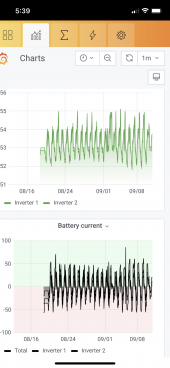
And where does a breaker actually trip and how long till it does. Or just go with a 200 breakers and put my values in the app settings and not over think it. I know Andy used only 100 amps on his, but that’s on the light side for me. As you can see in the screen grab of the last month, I don’t use a lot of amps 99% of the time but it’s nice to have it available if someone turns on the dryer and AC at the same time which we have avoided up to now.
Two breakers I’ve been looking at are the DIHOOL 160 or 200 amp single pole
 

Attachments

  • 252D3683-2EA3-4394-ABF7-8AEE20850D82.png
    252D3683-2EA3-4394-ABF7-8AEE20850D82.png
    793.1 KB · Views: 6
Last edited:
The JK '200 Amp' BMS units are capable of only a little bit more than 200A continuous output. IIRC, I saw a youtube video (at may have been "Andy") in which a JK BMS was "blown up" (burned MOSFETs) by running at only around 206A for multiple minutes. (His battery connection configuration sucked, BTW.) For much shorter periods (less than one second), these JK BMS units are probably good for about 350A. I use a 350A Class-T fuse (super fast) with my own JK-B1A8S20P unit, suporting a "12 volt" 4S battery with "200A continuous output" allowed for to not more than 2 seconds).

The JK BMS configuration parameters do not include a specific maximum "peak output current" value. Even if it did, I think that the situation the process of detecting and the then responding to over-current would be too 'slow' to save the output MOSFETs. That's the reason for using a fast-acting class-T fuse: The maximum continuous output current parameter (with it's over-limit timer tuned to the minimum value of 2 seconds), and the short circuit protection timer (with it's value tuned down to maybe 100-200 milliseconds) replace the functionality of a slow circuit breaker - but the class-T fuse is needed, especially in the case of parallel battery packs, to protect the BMS circuitry providing those over-current protection functions.

"Slow" circuit breakers are inexpensive, but they're pretty much much redundant with the BMS Over-Current protection mechanisms. Your graph isn't entirely clear to me, and your didn't describe your battery (voltage, in particular) or your Inverter layout (I'm not sure whether they are each supporting one side of the split-phase requirement, or whether each does 1/2 of the load on both hot legs.)

In either case they are roughly "equivalent" to the load caused by one bigger split phase Inverter with twice the current draw from a "shared battery bus" (which may not actually exist in your case). I'll attempt to work backwards from that scenario as follows:

If a 120/240 VAC Air Conditioner needs 55A on startup (55 * 240 Volts =13200 watts). If runnng at the same time, most BIG 120/240 clothes dryers pull around 25A. (25 * 240 volts = another 6000 watts). Input DC power would be 8-12% worse due to conversion costs. 19200w * 1.12 = would be 21,500 watts, assuming no 'peaking capability' provided by DC pre-load capacitors within the Inverter. All large Inverters can provide at least some of that, my calculation with none included is a possibly severe over-estimate.

Your battery voltage is of course critical. If I assume 48V as worst case, then I would get 448A on the DC side - and 2 '200A' BMS units would be greatly stressed, being HIGHLY over-utiized during rotor startup.

Please advise how your Inverter and battery configuration modifies my "225A" scenario.
 
My bank of 5 Packs (30kWh) with JK-B2A24S15P are all fused with 200A for each pack @ the Busbar using BlueSea MRBF-200 Fuses (Made by Eaton Fuses). The 200A BMS can do up to 350A Burst up to 2 minutes (per spec) but with batteries in parallel that's not going to pop up. The entire Bank is wired to a Master Breaker, Carling Technologies F-Series "Non-Polarized" 250A Breaker (As sold by Midnite Solar). Battery Bank & SCC (Midnite Classic-200) go to the INPUT Side of the breaker, the OUTPUT Side goes to the Inverter

Breaker Specs:
  • NON POLARIZED
  • Environmental Rating - Type 1 (Indoor)
  • Width 1.5 inches (39mm)
  • 125VDC Panel Mount Breaker - 3/8" studs
  • AIC 50,000 at 125VDC
  • Breaker Torque Value: 15 Ft-Lbs (20.4NM)
  • Includes two 10-32 x 3/8 Pan Head Phillips mounting screws
  • Warranty - 5 yrs.
  • Listed for US & Canada
REFS:


A Personal Note: While I have faith in High-Quality Breakers & Fuses, "Lessons Learned" has proven that nothing is a sure bet and it's best to cover your ass for the potential's, therefore having both Fuses for each pack + a Master Breaker is prudent. Also, it is a small price to pay to be on the safe side.

FOR YOU, I would suggest FUSES for Each Battery Pack (MRBF, or T-Fuses) and a Master Breaker Between the battery bank & Inverter/charger system. Also do not forget, that as you are increasing a Parallel Bank of batteries you are dividing the Load/Charge between them, reducing the odds of having something "pop".
 
The JK '200 Amp' BMS units are capable of only a little bit more than 200A continuous output. IIRC, I saw a youtube video (at may have been "Andy") in which a JK BMS was "blown up" (burned MOSFETs) by running at only around 206A for multiple minutes. (His battery connection configuration sucked, BTW.) For much shorter periods (less than one second), these JK BMS units are probably good for about 350A. I use a 350A Class-T fuse (super fast) with my own JK-B1A8S20P unit, suporting a "12 volt" 4S battery with "200A continuous output" allowed for to not more than 2 seconds).

The JK BMS configuration parameters do not include a specific maximum "peak output current" value. Even if it did, I think that the situation the process of detecting and the then responding to over-current would be too 'slow' to save the output MOSFETs. That's the reason for using a fast-acting class-T fuse: The maximum continuous output current parameter (with it's over-limit timer tuned to the minimum value of 2 seconds), and the short circuit protection timer (with it's value tuned down to maybe 100-200 milliseconds) replace the functionality of a slow circuit breaker - but the class-T fuse is needed, especially in the case of parallel battery packs, to protect the BMS circuitry providing those over-current protection functions.

"Slow" circuit breakers are inexpensive, but they're pretty much much redundant with the BMS Over-Current protection mechanisms. Your graph isn't entirely clear to me, and your didn't describe your battery (voltage, in particular) or your Inverter layout (I'm not sure whether they are each supporting one side of the split-phase requirement, or whether each does 1/2 of the load on both hot legs.)

In either case they are roughly "equivalent" to the load caused by one bigger split phase Inverter with twice the current draw from a "shared battery bus" (which may not actually exist in your case). I'll attempt to work backwards from that scenario as follows:

If a 120/240 VAC Air Conditioner needs 55A on startup (55 * 240 Volts =13200 watts). If runnng at the same time, most BIG 120/240 clothes dryers pull around 25A. (25 * 240 volts = another 6000 watts). Input DC power would be 8-12% worse due to conversion costs. 19200w * 1.12 = would be 21,500 watts, assuming no 'peaking capability' provided by DC pre-load capacitors within the Inverter. All large Inverters can provide at least some of that, my calculation with none included is a possibly severe over-estimate.

Your battery voltage is of course critical. If I assume 48V as worst case, then I would get 448A on the DC side - and 2 '200A' BMS units would be greatly stressed, being HIGHLY over-utiized during rotor startup.

Please advise how your Inverter and battery configuration modifies my "225A" scenario.

I can’t modify your summation. If only most teachers could convey a concept as well. Your dryer number is spot on for cold elements, but luckily I got the air conditioner’s inrush down to 21 amps. I’m probably in the window with both of the high current characters operating in unison and a low SOC. That’s hoping no one turns on the dishwasher microwave or coffee maker. Remembering the words drilled into my brain, “hope is not a plan”, so a fast T class 300 amp fuse and a 200 amp breaker per bms along with setting the apps to 200 amps but at the minimal time delay just might be a plan. The fuse idea has escaped me, probably because of the price.
 
Last edited:
My bank of 5 Packs (30kWh) with JK-B2A24S15P are all fused with 200A for each pack @ the Busbar using BlueSea MRBF-200 Fuses (Made by Eaton Fuses). The 200A BMS can do up to 350A Burst up to 2 minutes (per spec) but with batteries in parallel that's not going to pop up. The entire Bank is wired to a Master Breaker, Carling Technologies F-Series "Non-Polarized" 250A Breaker (As sold by Midnite Solar). Battery Bank & SCC (Midnite Classic-200) go to the INPUT Side of the breaker, the OUTPUT Side goes to the Inverter

Breaker Specs:
  • NON POLARIZED
  • Environmental Rating - Type 1 (Indoor)
  • Width 1.5 inches (39mm)
  • 125VDC Panel Mount Breaker - 3/8" studs
  • AIC 50,000 at 125VDC
  • Breaker Torque Value: 15 Ft-Lbs (20.4NM)
  • Includes two 10-32 x 3/8 Pan Head Phillips mounting screws
  • Warranty - 5 yrs.
  • Listed for US & Canada
REFS:


A Personal Note: While I have faith in High-Quality Breakers & Fuses, "Lessons Learned" has proven that nothing is a sure bet and it's best to cover your ass for the potential's, therefore having both Fuses for each pack + a Master Breaker is prudent. Also, it is a small price to pay to be on the safe side.

FOR YOU, I would suggest FUSES for Each Battery Pack (MRBF, or T-Fuses) and a Master Breaker Between the battery bank & Inverter/charger system. Also do not forget, that as you are increasing a Parallel Bank of batteries you are dividing the Load/Charge between them, reducing the odds of having something "pop".
 
Thanks for the info Steve
Rick had mentioned Andy’s video where he smoked one when running it just a little over 200 amps for a few minutes. I kinda had that video in my head when I opened this thread. I totally agree with the batteries in parallel and individually over current protect each battery.
I’ve used the little cubed fuses before when I had my boat and they worked fine but the link you provided had a curve of time and current that concerns me for this application. Thank god I sold that boat and don’t have to fill 400 gallons tanks lol. Those breakers are interesting but for another project.
 
Back
Top