thanks for your reply, top balance is close, 0.007A I think, granted, it does drift off as the cells discharge, but I'm not convinced this is the cause of the issue, when the BMS turns off due to OVP voltage, all of the other cells are way below the UVP-recovery/restart voltage, yet only as soon as the BMS (and inverter) are off, "discharge on" is seen on the JK app, and the inverter starts up again, runs for a couple of seconds, then cuts out due to the UVP.
my points/problems are :
1, once UVP triggers the BMS to turn discharge off (ie, no output to load) this should remain off until all cells reach UVPR, such that it can allow my solar to charge the battery to a point that I'd like to allow the load to connect again
THIS IS MORE THAN LIKELY THE CAUSE OF THE PROBLEM :
2, if my (tiny 4 amp) charger is connected, and simulating a low level of charging from the solar panels, this somehow causes the BMS to connect the load
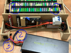
in the attached photo (check if you think this is the correct settup) :
"1" Pos/Neg come in from the pack, through the breaker and
pos goes through to the terminal, and neg goes through the BMS, BMS P- then to Terminal
"4" Obviously the main terminals, here is where the charger is connected, and solar (later) will connect
"2" Inverter connects to terminals, I'm currently trying to rebuild slightly as everything is too tight here.
"3" is the charger socket, and as you can see, it's connected straight to the terminals, could this somehow be in the wrong place ?
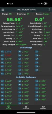
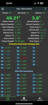
In the screen shots of the App below, bear in mind that for testing, I'd set the OCP to 4.0v, and the UVP to 3.1V (UVPR was set to 3.4v, and on a later test 3.6v, but the re-starting loop happened both tests)