diy solar

diy solar

JK BMS Doing Odd Things

i tried looking at this at the 48v section and i feel incredibly lost. i don't quite understand all the red lines and what they all mean. i did purchase these two if that at all helps in the time being..


the new bms and resisters arrive today at some point

i reached out to EG4 about precharging and this was their response, "As for the inverter needing to be pre-charged, that is not something that needs to be done."
The inverter doesn't need it.
Your bms seems to though.
 
The inverter doesn't need it.
Your bms seems to though.
with the resistors i'm getting, will that suffice for now? if so, what would be the proper procedure considering my setup. i see Will wrap it around the negative of the wire going to the negative..touch the terminal, then connect as normal.
 
with the resistors i'm getting, will that suffice for now? if so, what would be the proper procedure considering my setup. i see Will wrap it around the negative of the wire going to the negative..touch the terminal, then connect as normal.
That should work.
Does your inverter light up or beep when powered up?
If so just hold the resistor inline between the lug and stud until the inverter beeps then attach the wire.
Might want to wear a glove as the resistor body may get a bit warm.
Its also good practice to wear safety glasses while working with high current connections.
Yellow looks the coolest :)
my inverter is very noisy with all it's fans so i'll know. i'm hoping that bms arrives any moment now, any thing else i should do before connecting it and testing?
 
it seems that the new clamp meter, registers .005-.006 higher than the original meter i used to do tests, which was a klein mm400.

For example on Cell 16

BMS - 3.324v
MM400 - 3.331v
CL800 - 3.337v

not sure what to believe at this point
Not terrible.

I would also check at system voltage(48 volts).
If it were me I would go with the MM400 and not loose a minutes sleep over it.
If you have a friend with a fluke you could check your MM400 against that.
 
my inverter is very noisy with all it's fans so i'll know. i'm hoping that bms arrives any moment now, any thing else i should do before connecting it and testing?\
Inspect the balance leads to make sure they increment in voltage and that you have good connections.
Make sure that you didn't crimp the insulation.
What is the purpose of that buck converter?
 
What guage wire have you got on the ac input?
Is it landed on a dedicated breaker?
If yes, want amperage is the breaker?

Do you have the ac output wired?
What gauge wire?
 
Inspect the balance leads to make sure they increment in voltage and that you have good connections.
Make sure that you didn't crimp the insulation.
What is the purpose of that buck converter?
to power all my 12v dc items

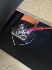
it does seem that the terminal connectors i crimped on..the insulation seems to protrude under the nuts slightly when i tighten them down. i don't know a way around that - they are the premade connectors below and i'm using the 22-18 pink ones. i used the 1/4" sized ones

https://www.amazon.com/gp/product/B07124B886/ref=ppx_yo_dt_b_search_asin_title?ie=UTF8&psc=1
Please post a picture that shows what you are describing.
I'm not sure I understand what you are saying.
Please make it bright, clear and high contrast.
 
What guage wire have you got on the ac input?
Is it landed on a dedicated breaker?
If yes, want amperage is the breaker?

Do you have the ac output wired?
What gauge wire?
ac in is 14ga, but i've capped my charge at 10a for testing purposes.
it's on a non dedicated 15amp breaker and i only have my computer plugged in currently.
ac output has a 12ga wire currently, but i'm not using it

the ac in is for testing purposes really. i have a dedicated 4ga / 50amp in the garage.

I would like to put a test load on the ac_out as well.
So if your computer is on the same circuit how do you disable ac_in to the inverter to idle draw, discharge etc?
 
I would like to put a test load on the ac_out as well.
So if your computer is on the same circuit how do you disable ac_in to the inverter to idle draw, discharge etc?
when i plug something in, how should i test the load?

the second question - i unplug the inverter when i don't use it, thats about as far as my brain has gone with it
 
you wanted me to test the load on ac out. is there something specific you want me to do to test the load?
Is there a receptacle on the end of that 12 awg wire?
If yes, is it nema 5-15R or 5-20R?
 
Back
Top