Apologies for temporarily removing this for a period. I found a few mistakes, too many, decided to pull it and redo.
Aim: DATA! The JK-BMS provides numerical data output for all the various voltages, currents etc. This data is easiest accessed via BLE. (Bluetooth). The aim is to get the data out of the BMS and into Grafana where we can review battery performance in realtime or historically.
The JK-BMS provides multiple interfaces from UART, CAN, RS485 and BLE. I only had a quick attempt at RS485 before finding it led nowhere fast. I found others had success with bluetooth. This is the approach I ended up sticking with as it yielded the best results in the least amount of time.
Items needed:
* A JK-BMS
* An ESP32 (dev board, Node32, WemosMini32, no GPIOs are required)
* Access to an MQTT broker
* Access to an InfluxDB instance
* Access to a grafana instance
* Ability to run some python code, or NodeRed if you wish
The "Access to" items I will briefly cover options.
Connecting the ESP32 to the BMS to get data.
The following github project contains a pre-made ESPHome component for the ESP32. ESPHome, in the sense of how we are going to use it here, is just an ESP32 programming and platform utility. We will only use it to program the ESP32.
https://github.com/syssi/esphome-jk-bms
Other than ignoring the UART wiring portion, if like me you intent to use only BLE. You are advised to follow the documentation above to get that working. I will tell you what I had to fiddle with to get it working on mine.
I choose the docker-compose route to install ESPHome. Using the following docker-compose.yaml
The volume mapping for the usb-Silicon_Labs USB_to_UART is the ESP32 board. There are other options to facilitate the docker seeing the USB adapter. I choose to volume map it.
You don't need to use docker-compose, I advise it, but you can just install ESPHome any other way as well.
I then cloned that github repo. I took the "esp32-ble-example.yaml" example config, copied it into the ESPHome "config" folder and edited the top portion only:
Name, describe it, change the MAC Address (get from app). Select which proto version your BMS supports.
Optional, but additionally I enabled direct MQTT support by adding a secrets.yaml int he config folder as:
Then uncommented the mqtt: section the main config:
If you multiple instances remember to change the "id:".
Flashing to the ESP32, assuming you have got a recognised ttyUSB or other UART device hooked up to it, I ran this:
Teething troubles aside it ran and produced text logging output including BMS data.
Checking the MQTT broker I found topics looking like this:
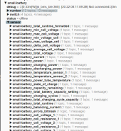
Number contains the configuration settings.
Switch is the third page on the app for turning stuff ON/OFF.
Sensor is where all the stats live.
At this point you should be able to unplug the ESP32 and move it closer to the BMS, somewhere between the BMS and the WIfi AP is good with good reception on both. You can also point HomeAssistant at it. If that is all you need, you are more or less dane.
Getting data to Grafana... Part 1, InfluxDB.
There are "off the shelf" MQTT to Influx "bridge" projects. Unfortunately I have not browsed these in quite a while having my own in house libraries for same. I will share the git repo link for the code I use, which is unfortunately in two parts. I strongly encourage you to seek a more mainstream project or maintain your own code for this, mine is a bit "janky" in this area with too much copy and paste laziness.
I transform the raw MQTT to a different format (JSON) and publish it to another MQTT. This step is not required, but without putting it here the next part will make no sense!

Then I load those transformed messages into Influx using the HTTP client API. Here:

In english:
Subscribe to the parent topic, say "small-battery/sensor/#
On receiving a message extract the "metric" from the topic, eg: small-battery_state_of_charge (optionally removing the prefix).
Form a JSON structure to conform with the InfluxDB HTTP REST API protocol.
POST that to the REST API using the influx client lib.
In short something like this:
You could also do this from NodeRed or similar application if you desire, whatever works.
Assuming you got the data into influx-db, the rest of the effort is in setting up your grafana dash boards.
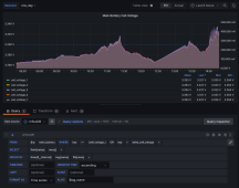
Here are a few snapshots of mine:
The Main JK_BMS dash (with a Cameo appearance of the MPPT stats and some ambient temp sensors).
(Yes, I am still trying to get a top balance finished We trying with the multiplus charger last night after the sun let me down yesterday).
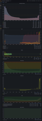
The realtime dashboard, "kiosk" style, single screen of the whole house.
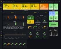
My docker-compose where I get all of this to run together as one platform:
Aim: DATA! The JK-BMS provides numerical data output for all the various voltages, currents etc. This data is easiest accessed via BLE. (Bluetooth). The aim is to get the data out of the BMS and into Grafana where we can review battery performance in realtime or historically.
The JK-BMS provides multiple interfaces from UART, CAN, RS485 and BLE. I only had a quick attempt at RS485 before finding it led nowhere fast. I found others had success with bluetooth. This is the approach I ended up sticking with as it yielded the best results in the least amount of time.
Items needed:
* A JK-BMS
* An ESP32 (dev board, Node32, WemosMini32, no GPIOs are required)
* Access to an MQTT broker
* Access to an InfluxDB instance
* Access to a grafana instance
* Ability to run some python code, or NodeRed if you wish
The "Access to" items I will briefly cover options.
Connecting the ESP32 to the BMS to get data.
The following github project contains a pre-made ESPHome component for the ESP32. ESPHome, in the sense of how we are going to use it here, is just an ESP32 programming and platform utility. We will only use it to program the ESP32.
https://github.com/syssi/esphome-jk-bms
Other than ignoring the UART wiring portion, if like me you intent to use only BLE. You are advised to follow the documentation above to get that working. I will tell you what I had to fiddle with to get it working on mine.
I choose the docker-compose route to install ESPHome. Using the following docker-compose.yaml
Code:
version: '3'
services:
  esphome:
    container_name: esphome
    image: ghcr.io/esphome/esphome
    volumes:
      - ./config:/config
      - /etc/localtime:/etc/localtime:ro
      - /dev/serial/by-id/usb-Silicon_Labs_CP2104_USB_to_UART_Bridge_Controller_02xx04D-if00-port0:/dev/ttyUSB0
    restart: always
    privileged: true
    network_mode: host
The volume mapping for the usb-Silicon_Labs USB_to_UART is the ESP32 board. There are other options to facilitate the docker seeing the USB adapter. I choose to volume map it.
You don't need to use docker-compose, I advise it, but you can just install ESPHome any other way as well.
I then cloned that github repo. I took the "esp32-ble-example.yaml" example config, copied it into the ESPHome "config" folder and edited the top portion only:
Code:
substitutions:
  name: small-battery
  device_description: "JK-BMS 8S Main Pack"
  external_components_source: github://syssi/esphome-jk-bms@main
  mac_address: 20:22:xx:11:09:xx
  # Defaults to "JK02"
  # Please use "JK02_32S" if you own a JK-B2A8S20P >= hardware version 11+ (f.e. JK-B2A8S20P hw 11.XW, sw 11.26)
  # Please use "JK04" if you have some old JK-BMS <= hardware version 3 (f.e. JK-B2A16S hw 3.0, sw. 3.3.0)
  protocol_version: JK02_32S
Name, describe it, change the MAC Address (get from app). Select which proto version your BMS supports.
Optional, but additionally I enabled direct MQTT support by adding a secrets.yaml int he config folder as:
Code:
wifi_ssid: mylan
wifi_password: EasyGuessedPassword

mqtt_host: 10.0.0.3
mqtt_username: user
mqtt_password: pass
Then uncommented the mqtt: section the main config:
Code:
mqtt:
   broker: !secret mqtt_host
   username: !secret mqtt_username
   password: !secret mqtt_password
   id: mqtt_client
If you multiple instances remember to change the "id:".
Flashing to the ESP32, assuming you have got a recognised ttyUSB or other UART device hooked up to it, I ran this:
Code:
docker-compose exec esphome esphome small_battery.yaml runTeething troubles aside it ran and produced text logging output including BMS data.
Checking the MQTT broker I found topics looking like this:

Number contains the configuration settings.
Switch is the third page on the app for turning stuff ON/OFF.
Sensor is where all the stats live.
At this point you should be able to unplug the ESP32 and move it closer to the BMS, somewhere between the BMS and the WIfi AP is good with good reception on both. You can also point HomeAssistant at it. If that is all you need, you are more or less dane.
Getting data to Grafana... Part 1, InfluxDB.
There are "off the shelf" MQTT to Influx "bridge" projects. Unfortunately I have not browsed these in quite a while having my own in house libraries for same. I will share the git repo link for the code I use, which is unfortunately in two parts. I strongly encourage you to seek a more mainstream project or maintain your own code for this, mine is a bit "janky" in this area with too much copy and paste laziness.
I transform the raw MQTT to a different format (JSON) and publish it to another MQTT. This step is not required, but without putting it here the next part will make no sense!

Then I load those transformed messages into Influx using the HTTP client API. Here:

In english:
Subscribe to the parent topic, say "small-battery/sensor/#
On receiving a message extract the "metric" from the topic, eg: small-battery_state_of_charge (optionally removing the prefix).
Form a JSON structure to conform with the InfluxDB HTTP REST API protocol.
POST that to the REST API using the influx client lib.
In short something like this:
Code:
 json_body = [
        {
            "measurement": measurement,
            "tags": {
                "key": device,
                "type": type
            },
            "time": dt,
            "fields": {
                "value": state
            }
        }
    ]
    write_json(json_body)


def write_json(json_body):
    client.write_points(json_body)#, retention_policy="one_year")
You could also do this from NodeRed or similar application if you desire, whatever works.
Assuming you got the data into influx-db, the rest of the effort is in setting up your grafana dash boards.
Here are a few snapshots of mine:
The Main JK_BMS dash (with a Cameo appearance of the MPPT stats and some ambient temp sensors).
(Yes, I am still trying to get a top balance finished

The realtime dashboard, "kiosk" style, single screen of the whole house.

My docker-compose where I get all of this to run together as one platform:
Last edited:


