diy solar

diy solar

JK BMS SoC?

I don't really see this leaking of power. That said, I have not been checking this in great detail since quite a while ago, so I don't know if something changed in the mean time.

I must protest that Cell Voltages manifestly do relate to State of Charge, although the voltage changes which must be measured vary by relatively small amounts within most of the 'working range' of LFP battery cell voltages.

Let me rephrase then :) : For all practical use cases of determining state of charge on the battery, voltages don't matter except at the knees.
 
I don't really see this leaking of power. That said, I have not been checking this in great detail since quite a while ago, so I don't know if something changed in the mean time.
I was joking about mysterious "leaks into the aether". The Bluetooth App "status" shows nearly vanished capacity, while the battery still has more than 65% of capacity left.

Long explanation of a maybe-too-subtle joke: Early in the 19th centurym, Aether was originally 'conceived' in a misguided attempt to explain how light "waves" could travel through empty space. As a physics student, dozens of years ago, I was made to repeat the Michelson-Morely experiment in a safer and more modern version - in the same room where Michelson later conducted the famous "oil drop" experiment. (I re-did that one too.) As in the original experiment, where specific and large measurable properties of the "Aether Fluid" should have appeared, virtually no evidence of Aether was exposed. (Predicable effects of its presence were not observed when the apparatus was turned, changing the path through the fluid. Very similar to the the "Dopper Effect" changing the pitch of sound from a passing train.) Aether absolutely doesn't exist, so the JK can't possibly be "leaking power" into that magical mystery fluid, determined to be a fantasy roughly 150 years ago. :ROFLMAO:
Let me rephrase then :) : For all practical use cases of determining state of charge on the battery, voltages don't matter except at the knees.
If your volt meter is accurate to a couple of thousandths of a Volt (and mine is), you can make practical judgements within the midrange. But I'll be using an external coulomb counter. The JK-reported numbers become more erroneous every single day, pretty quickly reaching a state with 'bogus' low SOC figures. After just one day of sitting unused, my JK numbers become wrong (and basically useless).
 
Last edited:
With the highest respect (because you're THE BEST :giggle:) I must protest that Cell Voltages manifestly do relate to State of Charge, although the voltage changes which must be measured vary by relatively small amounts within most of the 'working range' of LFP battery cell voltages.
I don't think you'll find very many people here who agree with this statement. In the case of LiFePO4 (and in fact, most Li-based chemistries), the majority of the SoC range has a very flat voltage curve.

Try this experiment, or at least visualize it. Take 4 cells that you have confirmed have very nearly the same capacity. Separately, run them partially down to different SoC's, perhaps by using your capacity load tester. Run one down to 45%, one to 50%, one to 55%, and one to 60% SoC. Now wire them all in parallel and leave them that way for a couple of days. When you disconnect them (and let them rest) they will still have very nearly the same voltage. Now hook them up in series as a 12V battery, and start charging, watching the individual cell voltages. What you will see is that the cell that had been the 60% SoC cell will break through the upper knee before the others, and each will follow based on their SoC order. I'm not saying that after the cells have been connected in parallel they will remain at 60%, 55%, 50%, and 40% SoC levels. However, the nearly identical voltages when starting the series charge will not translate into nearly identical SoC's. This in fact is why we top balance, rather than just balance at some mid-point in the voltage curve.
 
I brought three JK BMS online 3 weeks ago. Until they went through a full discharge to shutoff cycle, they were inaccurate. I went to bed with 28% remaining battery, estimating that at current load I had more than enough til sun up, and 3 hours later my wife wakes me to say there's no electricity. I go down to find all three battery banks at zero. Now I'm running at 8% charge and it's decreasing at a more linear rate because the BMS "learned" the discharge cycle of my battery bank.
 
I brought three JK BMS online 3 weeks ago. Until they went through a full discharge to shutoff cycle, they were inaccurate. I went to bed with 28% remaining battery, estimating that at current load I had more than enough til sun up, and 3 hours later my wife wakes me to say there's no electricity. I go down to find all three battery banks at zero. Now I'm running at 8% charge and it's decreasing at a more linear rate because the BMS "learned" the discharge cycle of my battery bank.
What's a full cycle? Full to empty and back again?
 
If you enter the AH of battery (and it is correct for given battery) you only need to do a full charge to the BMS coulomb counter reset voltage. This is usually set to slightly below charger absorb voltage setting. When battery is charged to this trigger voltage level the monitor should reset to 100% full. This establishes a fresh full reference. You might see monitor jump from a lower SOC % immediately to 100% SOC when it hits this charge voltage level.

Some of the BMS have an automatic AH determination but it takes a full discharge where voltage knee drops off. It takes the cumulative count at this point to fill in the AH setting. This only works if battery was also fully charged before discharging to reset counter to 100% full. I prefer to set AH manually. You can set battery AH a little lower than actual to give yourself some safety reserve margin before total battery depletion drop out and BMS shutdown occurs. You still have to keep cells balanced. Taking to absorb charge voltage for a couple of hours periodically will provide balancing time and reset 'full' reference.

If you only do repeated partial charging for a long period, the monitor will cumulate more errors is SOC count over time. The full charge to 100% battery reset trigger voltage resets the 100% reference point, clearing cumulative errors. If you don't charge to this trigger voltage periodically the monitor is only adding and subtracting discharge and charge current which have some errors that will accumulate over time degrading SOC readout accuracy.
 
What algorithm does JK use to determine 100% SOC , there are various ways implemented out in the battery world and they all must include a "reset " as couloub counters will eventually drift to a point of not being usable - Victron use a both a voltage and threshold current , I cannot fathom out what JK use - mine never gets over 98 % . I suspect it might be to do with voltage cutoff limits perhaps - can anyone confirm this
 
What algorithm does JK use to determine 100% SOC , there are various ways implemented out in the battery world and they all must include a "reset " as couloub counters will eventually drift to a point of not being usable - Victron use a both a voltage and threshold current , I cannot fathom out what JK use - mine never gets over 98 % . I suspect it might be to do with voltage cutoff limits perhaps - can anyone confirm this
The Algorithms are Proprietary and not published. They do use the Coulombmeter along with "pack" & cell voltage resolutions.
It takes 3 to 4 full charge/discharge cycles and is in fact about 99% accurate afterward's, which dos self-correct as well.

Where many DIY'ers trip, is the understanding of "what" is 0% & 100%, which is the single largest point of confusion resulting in odd results. This in fact applies to virtually ALL BMS' and battery systems.

PLEASE refer to the Posting Below.
 
Thanks Steve , yes I am using 3.425V and often do not charge to that as it depends on Solar and my 3 day solar outlook. - if solar looks good for the next 3 days I do not charge to "100 % " often to only 70- 80%SOC - so not sure if JK proprietary algorithms will handle that
 
Thanks Steve , yes I am using 3.425V and often do not charge to that as it depends on Solar and my 3 day solar outlook. - if solar looks good for the next 3 days I do not charge to "100 % " often to only 70- 80%SOC - so not sure if JK proprietary algorithms will handle that
Please remember that 3.425Vpc is NOT the 100% of Working Range, it is approximately 96% of Gross Range which is entirely acceptable. That 10% B=ottom - 19% from Top is NOT what many get befuddled over, that is a LEGACY Shtick that will NOT go away.

FYI, By NOON I am at 100% and @ Float is then carrying ALL my Loads (Unless really heavy). IF Loads dip into the Battery Bank, then Float up's it's amps and trickles back to 100% fairly quickly.
I am in North Eastern Ontario Canada and my Sunhours are pretty funky in general. But it ALL works 100% Bang on the money for 90% of the year (deep winter, well white shit happens and Ces't La Vie.)

Steve_S
 
Is ability to use SOC% that critical?

Maybe just do this:
Would it be possible to add a feature to just manually start a new cycle? That is, when I know the battery is at 100%, just reset the coulomb counter so that the reading at that point becomes just 100%, xxxAh remaining.
Kinda simple IMO.

Deye does this; when Batt Voltage reaches my predetermined Absorption Voltage, it resets SOC to 100%; it decrements SOC% by the amount of AH discharged and increments SOC% by the amount of AH charge added thereafter.
 
Your Jk BMS should calculate the SOC automatically in seconds, mine does,in all situations,but only in %; the rest,the Ah, it does it too,but that depends entirely on your manual input on line 2 of screen 2, it cannot know the avg capacity of your cells without you telling it;

My jk bms,bought in Aug/2022 is an amazing tool, did i say amazing...

The model is JL_B2A8S20P,and it had 121 update versions before, just click on the 3 dots ,any of the 3 screens,to see yours
And it is just Amazing,it determines,it knows, the SOC ,state of charge, of the pack,in percentage,only, in seconds, in any situation, empty,full,in between, charging,discharging, at rest, etc;
from there,from the %, it just does a simple math, and gives out a reading of the soc Ah, but that is accurate only if you had previously manually input (screen 2 line 2!!) the correct,or very approximate, full capacity of one cell,in Ah,say 300Ah,or what have you;

It does this feat, outstanding to me, (but I may stand corrected º.º) thanks to a lot of work performed by the engineers at Jikong(?) bms( i never had any other one ,but i assume(?) that all other brands are the same?),them JK engineers, they took their sweet time to produce lengthy charts and tables for all possible situations and combinations with the Lifepo4 Chemistry, Volts( down to sub millivolts,due to the relative flatness of the curves), Amps, and Direction,in or out; armed with this,the software instantly computes the SOC in % and then to Ah,as said.

You mileage may vary,but mine is,so far,a good BMS; the only thing i do not like on it, is the fact the the Bluetooth Module is just built-in,instead of being external and at the end of a cable, so that i could better position it for a bit of a longer range; the way it is,it's auto-limitting; if anyone has a possible solution for this i would love to know about it.
 
The JK documents does not state what parameter is used to reset coulomb counter.

It would be very dumb to use its calculated % SOC to reset the counter. That would be a case of 'the blind leading the blind'.

With BMS having the ability to read every cell voltage I am pretty sure it resets when ALL cells are above a given voltage. Since BMS also has ability to measure battery current it could also put as a criterion that each cell reaches a given voltage at a low charge current level. This would ensure high charging current is not impacting cell voltage readings.

Question is what this reset trigger voltage is. Since there is not a specific user setting with this parameter name, I can only assume it is a scaled value from one of the other user settings, likely perhaps a fractional percentage of maximum cell overvoltage setting.

Since JK BMS can be used with different Li-Ion chemistries, it cannot be a firmware hard fixed value and must be derived from one of the user set inputs. I guess it could be derived in a hard fixed way by what you set for battery type setting.

It would be nice to know, or figure out by experiment, which user parameter this Colomb counter reset is derived from.

I did send an email to them asking about this but got no response.
 
Last edited:
Thanks for your reply;
Not dumb if the determined SOC, in % , is accurate; which i think it is.
High,low,very low,Very High, charging or discharging currents, of course DO impact volts readings, by a lot,and therefore the SOC determinations too; but that does not matter IF you know the Amps direction and by how much,all you need then, is,From Previous Numerous Tests, an exhaustive chart,with all sorts of possibilities, not easy to do,but i'm sure it has been done,i find no other explanation for the workings of my BMS,

I´ll bet they not use Coulomb counter alone, i read that it does not work well in the long run due to cumulative errors; in fact i am pretty sure of it, i daily verify that they don't, since the SOC is determined in an instant without any previous knowledge of history of volts or amps;

This is from the manual of the bms i have, very useful things to keep in mind ( they confused the issues with the 2 meanings of the word "current" used too many times, so i cut some off, you can see the confusions in the original manual in the net);

e) Voltage The voltage area displays the total voltage of the battery in real time, and the total voltage is the sum of all cell voltages.
f) Current The current area displays the total current of the battery in real time. When the battery is being charged, the current is positive, when the battery is being discharged, the current is negative.
g) Battery power Represents the total power output or input of the battery, and its value is the product of the battery voltage and the absolute value of the battery current.
h) Remaining battery Indicates the percentage of battery power remaining.
i) Battery capacity Represents the actual battery capacity calculated by the high-precision SOC of the current protection board, and the unit is AH. (This value needs to be updated after the battery has completed a complete discharge and charge cycle).
j) Remaining capacity The remaining capacity represents the remaining capacity of the battery, unit: AH.
k) Cycle capacity Cycle capacity represents the cumulative discharge capacity of the battery, unit: AH.
l) Number of cycles The number of cycles indicates the number of times that the battery is fully charged, and the unit is: times.

note in i) "calculated by the high precision of the BMS board" that is what they mean, and i fully agree with it, hi precision...

And now this from the dr google who heard it from a friend,who heard it from...

TEST LIFEPO4 soc voltage coulomb

JP
Jose Peixoto


Thu 10/20/2022

TEST LIFEPO4
1))There are two main methods of battery fuel gauging: coulomb counting and measuring open circuit voltage (OCV).
Coulomb counting is the process of estimating the amount of charge used by measuring the charge going into and coming out of the battery. While this works well in the short-term, a small drift error increases continuously over time and the battery needs to reach full and empty periodically in order to correct these errors.

2))Another way to monitor the state of charge (SOC) of a battery is to measure the open circuit voltage. OCV is estimated by measuring the immediate voltage and by running a real-time simulation of the battery model using battery characterization and past voltage history. Because OCV is reliably related to a battery’s SOC, the former can be used to determine the latter. This method is more accurate because it does not suffer from capacity drift over time and uses less power because it does not require a current sense resistor.

3))Coulomb counting offers better short-term accuracy, while OCV is better for long-term.
To provide better results over a wider range of applications, these two methods can be combined with algorithms which uses the OCV algorithm to periodically remove the offset error introduced by the coulomb counter while maintaining the stability of a voltage-based fuel gauge.
The type of battery fuel gauge you’ll want to use will depend on your application.
d this is from somewhere from dr google who heard it from a friend,who...

To me, in 2)), they don't almost know what they are talking about, because OCV (open circuit voltage ) because OCV is not readily available in real life with our connected batteries; and real working voltages,they depend greatly on the CURRENT going in and out; current can easily be 10 amps, 100 amps,200 amps,what have you,and if you try it, you see that the SAME cell voltage swings wildly (up to 1000 millivolts) one way or the other,so to rely on that,you need a LOT of previously made charts; and that is,in my opinion, what Jk does along with coulomb counting,the manual does state that they also use coulomb counting.
 
Coulomb counting SHOULD be correct, either internal to the JK or externally. (They really should agree.) But my experience has been JK showing SUBSTANTIALLY reduced SOC over a period of 5-20 hours,, then slowly recovering back - even when battery cell voltages are unchanged (within .001 volts) throughout that period.

Keep in mind that two issues are present in my installation:
  1. The external counter is connected at P- (rather than B-), it is therefore unaware of power spent within the BMS itself.
  2. My JK BMS (1A, 8S, 200A with heat) is among the first production models of that unit ever built. It has an older microcode level, and I am unable to talk about the behavior of newer BMS units running with newer levels of microcode.
My JK reading cannot be reset or modified (without pushing cell voltages all the way to the top and bottom 'cutoff' voltage settings). JK "SOC" has appeared less accurate, both in storage and in multi-day RV trips, where each day typically consists of charging to either 13.4V or 13.6V (4S) and then slightly lower voltage and then using battery power through the evening and into the early morning. In my normal use during RV trips, I have MPPT charging only, the float voltage is easily modified from 13.4V up to 13.6V when I anticipate "heavy" overnight usage. (Although the additional power stored between those two voltages might not really be worth the trouble.)

With plug-ins or with a generator, my less controllable RV power converter wants to push the battery voltage to about the same 13.6V measurement. However, in storage after about 14 days of non-use, my otherwise "dumb" RV power converter drops to 13.2 volts (3.30V per cell) for "storage". My storage is inside a dark garage, RV solar panels and MPPT supply nothing during storage.

With each 'overnight use' during a trip, JK shows substantially lower SOC than the external coulomb counter, both at maximum and at minimum. The difference is often in excess of 500wh (battery capacity about 2900 with the JK App showing an SOC value more than 15% lower than the external counter). The JK is definitely not consuming that difference - about 70 watts, it would be hot!!! too the touch if it were. And, to the extent that the overnight usage reaches into a non-linear portion of the SOC curve, the higher external coulomb counter value looks a lot more accurate than the JK App values. MPPT charging input power on the following day, as measured by the MPPT itself, includes some power spent during the day - but also seems to be a near-match for the external coulomb counter, rather than the JK value.
 
Last edited:
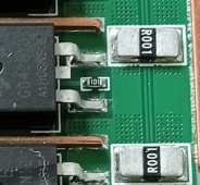
The JK BMS is a Chinese design, meaning every penny of manufacturing cost is carefully considered. The shunt chip resistors are cheap and then there is all the high current carrying solder joints for the ten of them in parallel.

You can have one of the ten chip resistor bad. A poor solder joint on one of them, or even a single bad MOSFET causing the PCB current distribution to shift causing variance on how the distributed chip shunt resistors picks up the current.

A clip-on DC amp meter is seldom better than 1% accuracy so not the best thing to use for a reference current reading. An external shunt monitor would be more accurate for measuring current.

The first thing is to check if the JK BMS is reporting the correct current for various current levels from low level to high level currents. If it does not report correct current then SoC calculation will also be incorrect. If current is wildly off it may mean a defect in a component or solder joint in BMS.

Be aware, if current load is created by a sinewave inverter it has a lot of 2x AC frequency ripple on battery line DC current that must be average filtered by any measurement device. BMS and battery monitors have a few hertz bandwidth low pass filter to average out the ripple. A clip-on DC amp meter may not have sufficient filtering for this ripple current effecting its reading.

The JK BMS does allow recalibration of current reading but the current you select for calibration matters. If you calibrate at low current it will be poor accuracy at high current, if you calibrate at high current it will be poor accuracy at low current. You should select a current to calibrate based on your typical average use current. The better the device used to measure actual current accurately, the better the recalibration of BMS will be.
 
Last edited:
Hi guys!

After having a similar need to recalibrate JKbms i ended up here :)

You can somewhat trick the BMS without going trough a full cycle if you change the AH settings to a higher capacity (eg i changed mine from 230AH to 280 and it displayed 75-80% SOC). This will only work for top balancing and calibration, but i hope it helps.

One it reaches the over voltage protection will assume it;s 100%SOC, but it's a lot shorter to calibrate from almost there to ~90% where I was for example :)
 
The JK BMS is a Chinese design, meaning every penny of manufacturing cost is carefully considered. The shunt chip resistors are cheap and then there is all the high current carrying solder joints for the ten of them in parallel.

You can have one of the ten chip resistor bad. A poor solder joint on one of them, or even a single bad MOSFET causing the PCB current distribution to shift causing variance on how the distributed chip shunt resistors picks up the current.

A clip-on DC amp meter is seldom better than 1% accuracy so not the best thing to use for a reference current reading. An external shunt monitor would be more accurate for measuring current.

The first thing is to check if the JK BMS is reporting the correct current for various current levels from low level to high level currents. If it does not report correct current then SoC calculation will also be incorrect. If current is wildly off it may mean a defect in a component or solder joint in BMS.

Be aware, if current load is created by a sinewave inverter it has a lot of 2x AC frequency ripple on battery line DC current that must be average filtered by any measurement device. BMS and battery monitors have a few hertz bandwidth low pass filter to average out the ripple. A clip-on DC amp meter may not have sufficient filtering for this ripple current effecting its reading.

The JK BMS does allow recalibration of current reading but the current you select for calibration matters. If you calibrate at low current it will be poor accuracy at high current, if you calibrate at high current it will be poor accuracy at low current. You should select a current to calibrate based on your typical average use current. The better the device used to measure actual current accurately, the better the recalibration of BMS will be.
I think you are 100% correct,but, at least in my JK BMS ( it's 4or 5 months old, i saw it had over 20 revisions since the first issue) THERE IS SOMETHING ELSE they have done... they are just TOO damm accurate; and i am quite sure i know how it was dine; but i think you might have hit the nail right in the head with those solder deals yoy mention; "Protection-Current Sensor Malfunction" was displayed 2 or 3 times as i switched on an unusual heavy load, and it went from 30 or 40 Amps Charging to 50 or 60 Amps Discharging in a split second; i think it's a 150 amp BMS; when it does that,it halts all charge and all discharge, and resumes some time later,have not determined exactly when and how; if i manually (on the cell phone-bluetooth) shut it off and on, it resumes working well; and all this to say that,since i used to,among other things,many...,do some electronics repair, i may someday open it up and look at all solder joints, redo and reinforce them as needed; and so, i thank you for your teachings on the matter, i had a suspicion of something like that,just was resisting to open it, it has been working almost perfectly,and i just hate it when i have to go over what a factory has done,and redo things, but that has been my life all along: to revive the dead.
 
i may someday open it up and look at all solder joints, redo and reinforce them as needed; and so, i thank you for your teachings on the matter, i had a suspicion of something like that,just was resisting to open it, it has been working almost perfectly,and i just hate it when i have to go over what a factory has done,and redo things, but that has been my life all along: to revive the dead.

I opened up several ones here:


and here:


I my opinion as an electronics engineer, the soldering work on these boards is pretty damn good.
 
I my opinion as an electronics engineer, the soldering work on these boards is pretty damn good.
The JK active balancer BMS are continuously changing things on their BMS.

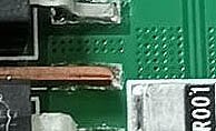
They have two rows of 'laced' MOSFET's, on each PCB side, with a jumper wire running between the opposite rows. These jumpers used to be round wire, fully end tinned, and hand solder. Assumedly to reduce labor cost, they have changed to narrow rectangular bare copper bars reflowed to board.

Keeping these bars straight enough to get a good surface attachment solder reflow at the end is difficult so there will be more or less solder thickness under the copper bar. The reflow solder also only tacks at bottom of bare copper bar surface which is not a great low resistance joint. The mechanical strength of this surface only solder joint is poor. The original round wires were pre-tinned all-around the wire end and hand soldered.

Regulations require all soldering be made with no-lead solder which has a higher reflow temperature and is more brittle than older lead-based solder.

The MOSFET's are continuously subjected to heating and cooling with the amount of passed current and the solder joints on these long copper bars are going to be subjected to a lot of mechanical expansion/contraction stress.

In short, I don't trust the new narrow rectangular shaped, bottom surface only reflowed, jumper bars.

Old version
JK bms original jumper wires.jpg

New version
Copper jumper bars with G042N10 MOSFETs.jpg Copper jumper bars with G042N10 MOSFETs 2.jpg
 
Last edited:
I've only gone in-depth on the ones I have here, and I tend to use the 100A version. I've not opened my 200A version (in storage) and have not kept up with recent versions. I'll have to buy a few to see what's up...
 
I also had the problem that my 16S2P Lifepo never "got to 100%" because in the utils.py from the serialbattery driver I had the settings well below the maximum value of 3.65V/cell (max. 3.47V/cell, 120x60 sec. absorption and then to float 3.4V)

As a result, the JK BMS usually displayed below 90% when it was switched to float. If you let the system run like this all the time, SOC drifts away more and more.

At times, when switching from absorption to float, the BMS only displayed an SOC of 67%, although the correct SOC was around 97%.

The culprit is that the SOC is never reset to 100%.

Then I lowered the OverVoltageProtection (OVP) in the JK BMS from the default 3.60V to just above my absorption voltage and the utils.py from 3.47 - i.e. to 3.49V. And now the SOC WILL be set to exactly 98% every sunny day when the battery has reached my desired "full charge state" and has been somewhat correct since then (since it can no longer drift so much due to the lack of commutation of the errors). (If you charge up to the OVP alarm of the BMS, in my case to 3.49V then the SOC goes to 100%)


Here are my settings: (The reduction of the charging current above 3.4V is important, since the balancing (starting at 3.4V) only works well if the charging current is not too high.)

# Set Steps to reduce battery current. The current will be changed linear between those steps
CELL_VOLTAGES_WHILE_CHARGING = [3.49, 3.45, 3.40, 3.30]
MAX_CHARGE_CURRENT_CV = [ 0, 8, 16, 120]

######### SOC limitation #########
# Description:
# Maximal charge / discharge current will be increased / decreased depending on State of Charge, see CC_SOC_LIMIT1 etc.
# The State of Charge (SoC) charge / discharge current will be in-/decreased depending on SOC.
# Example: 16cells * 3.45V/cell = 55,2V max charge voltage. 16*2.9V = 46,4V min discharge voltage
# Cell min/max voltages - used with the cell count to get the min/max battery voltage

MIN_CELL_VOLTAGE = 3.00
MAX_CELL_VOLTAGE = 3.47
FLOAT_CELL_VOLTAGE = 3.40
MAX_VOLTAGE_TIME_SEC = 120*60


Another note: I had to turn off the "LINEAR_LIMITATION_ENABLE" option (set it to False) because it kept switching back and forth between "discharging" and "charging with 25A and more" when the cell voltage levels were high, which made top balancing almost impossible.
 

diy solar

diy solar
Back
Top