diy solar

diy solar

Hankzor JK BMS with screen and power button

Ok, update time. Finally had some time to have a look at the new BMS.
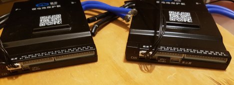
20220127_205414.jpg

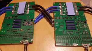
The new one on the right, old one on the left. They're both 100A versions to keep the comparison easier. The port to the right of the GPS/RS485 label is the display port. As Dave Jones would say: "Don't turn it on. Take it apart!"
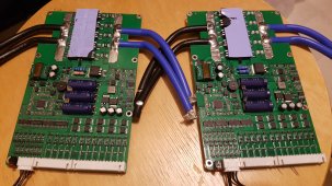

20220127_205814.jpg
New one on the right again. The original is hardware version 6.0, the new one 8.0. There have been a few changes, mostly on the other side of the board. The main change on this side of the board is the micro controller. The old version had an original STM32F103; probably due to shortages or because more resources were needed, it is replaced with a GD32F103. This is a pin compatible clone of the STM, it's used on some Bluepill boards and finds its way into many products these days since it's cheaper and actually available, unlike the STM. It also has more RAM/FLASH and can run at higher clock speeds. I'm actually surprised they didn't have the GD32 on there from the beginning. The MOSFETs are still the same: G042N10.
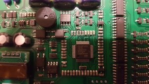

20220127_210309.jpg
The GD32.

20220127_210904.jpg

Other side of the board. More profound changes here. For one, the Bluetooth module was changed. Didn't look at the details, but they're both common modules. The chip at the bottom is a YD3082, which is an RS485 transceiver, which is what is driving the display. I'm not sure yet if this shares the same RS485 bus where one connects the RS485 dongle to. I'll find out later. There are also some added digital isolators that weren't there before (an 122U31) - probably to provide better isolation between the power and control side.
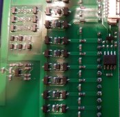
20220127_211016.jpg
The YD3082 RS485 transceiver in the middle to the right.

This is the Display itself. It's very clear and bright, and the power button on the side works fine to turn the BMS on. I somehow wish it could be used to turn the BMS off again, but that's not a deal breaker. Ignore the 6.6V and state of charge, I just connected the BMS to two spare cells and a power supply.
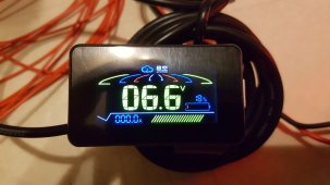
20220127_214612.jpg

I originally wanted to create a custom enclosure for it, but the handle bar mount can be removed easily, and it looks much better this way.
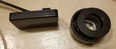
20220127_221412.jpg

Of course, I also opened the display:
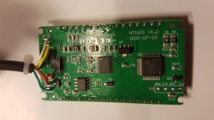
20220127_221155.jpg
It's based around a Holtec HT1621 display driver on the right. This thing has a serial interface, and the other chip to the left is a hk32f030, another microcontroller that takes the incoming data and talks to the Holtec chip.
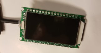
20220127_221143.jpg
The LCD display itself.


I want to dig in deeper in some of the changes and other aspects of the BMS. For one, I really want to figure out how the power button is implemented, and if this is a software or hardware thing (or both). I don't know when I will have time for this though; now that I have one sitting on my desk I want to get back to the RS485 communication, finishing my Grafana interface and then go to the next step: implement a supervisor which has a full overview of all components and their status, and can make decisions based on this...
 
Last edited:
Thanks for the great writeup.
I cannot find it now but on the a description that I found on the display, it said (if memory is correct) that you could turn the BMS off by "long pressing" the button. I cannot remember the time but I have several other devises that turn off with a 3-5 second press and hold on the button.

Yeah, I tried that, didn't work.
 
Ok, update time. Finally had some time to have a look at the new BMS.

View attachment 81464

The new one on the right, old one on the left. They're both 100A versions to keep the comparison easier. The port to the right of the GPS/RS485 label is the display port. As Dave Jones would say: "Don't turn it on. Take it apart!"


View attachment 81465
New one on the right again. The original is hardware version 6.0, the new one 8.0. There have been a few changes, mostly on the other side of the board. The main change on this side of the board is the micro controller. The old version had an original STM32F103; probably due to shortages or because more resources were needed, it is replaced with a GD32F103. This is a pin compatible clone of the STM, it's used on some Bluepill boards and finds its way into many products these days since it's cheaper and actually available, unlike the STM. It also has more RAM/FLASH and can run at higher clock speeds. I'm actually surprised they didn't have the GD32 on there from the beginning. The MOSFETs are still the same: G042N10.


View attachment 81466
The GD32.

View attachment 81467

Other side of the board. More profound changes here. For one, the Bluetooth module was changed. Didn't look at the details, but they're both common modules. The chip at the bottom is a YD3082, which is an RS485 transceiver, which is what is driving the display. I'm not sure yet if this shares the same RS485 bus where one connects the RS485 dongle to. I'll find out later. There are also some added digital isolators that weren't there before (an 122U31) - probably to provide better isolation between the power and control side.

View attachment 81469
The YD3082 RS485 transceiver in the middle to the right.

This is the Display itself. It's very clear and bright, and the power button on the side works fine to turn the BMS on. I somehow wish it could be used to turn the BMS off again, but that's not a deal breaker. Ignore the 6.6V and state of charge, I just connected the BMS to two spare cells and a power supply.

View attachment 81470

I originally wanted to create a custom enclosure for it, but the handle bar mount can be removed easily, and it looks much better this way.

View attachment 81471

Of course, I also opened the display:

View attachment 81472
It's based around a Holtec HT1621 display driver on the right. This thing has a serial interface, and the other chip to the left is a hk32f030, another microcontroller that takes the incoming data and talks to the Holtec chip.

View attachment 81474
The LCD display itself.


I want to dig in deeper in some of the changes and other aspects of the BMS. For one, I really want to figure out how the power button is implemented, and if this is a software or hardware thing (or both). I don't know when I will have time for this though; now that I have one sitting on my desk I want to get back to the RS485 communication, finishing my Grafana interface and then go to the next step: implement a supervisor which has a full overview of all components and their status, and can make decisions based on this...
wonderful write up!

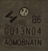
interesting that the G042N10 MOSFET is used here.

thank you for taking time to document these details!

on the JBD 120A 4S that i have, the MOSFET are labeled G013N04. fun to learn which switch is in which BMS. thanks

https://diysolarforum.com/threads/j...-lifepo4-in-series-parallel.19228/post-332656

based on the model number, perhaps Huayi makes the MOSFET in this JK BMS as well.
1643324760387.png
1643324749465.png
reference from other BMS
 
Yes, here too:


This one above had the G035N10N - also 100V, but higher max current.
 
Yes, here too:


This one above had the G035N10N - also 100V, but higher max current.

The MPP Solar inverters have 75V MOSFETs :)
 
One other thing I don't like about the screen: it's a (in relative terms) power hog. When active, it consumes 960mW, and when the display if off (but connected) it's 320mW. As someone who designs low power embedded systems, this is unacceptable. I'll probably add a power switch for the screen if I decide to use it, or I might be tempted do design my own screen for this BMS...
 
Ok, on the power consumption, it seems that after a while the screen draws 320mW in a pulsed pattern, and then some time later drops to 0mW altogether. The button wakes up the screen just fine and once it goes back to sleep it draws 320mW again, starting the pulsed pattern again after a few minutes and then back to 0mW. I guess there is some sleep code that only kicks in after some minutes. I'll add it to the list of further investigations needed...


Edit: Display keeps coming up and draw 320mW after some time, cycling pulsed pattern, etc. Never staying at 0mW... definitely needs a power switch in my opinion.
 
Last edited:
I've updated my repo to read the data from the BMS for Grafana display.

I look at your RS-485 code and my poor brain starts to smoke. I have not needed to do any real programing since collage and that was in Fortran with punch cards.

I recently installed a bunch of NMEA 2000 electronics on my boat. My understanding was that NMEA 2000 is basically CAN bus with funny connections to make it more "marine". I was hoping that connecting a BMS to an inverter would be as simple as connecting a chart plotter to a wind instrument which basically involves plugging each into the NMEA back bone and answering the questions on the Wizard that pops up.
Looks like it is more involved that that, sigh!
 
NMEA 2000 (I mostly know it as IEC 61162-3) is essentially plug an play. However, to do that, there is a whole lot of higher level functionality on top of the physical CAN bus and protocol. That RS485 code you see on my github is essentially something that lives right above the hardware, where we take incoming data bytes and decode those bytes according to a protocol description of what byte means what, in what order, how many need to be grouped, etc.

That said, you don't have to connect an inverter to the BMS. They work fine independently. But yes, if you want the BMS to control the inverter, etc. there is more involved unless you go with specific hardware that supports this (like Batrium BMS with Victron hardware).

Serial is fun for sure!
Nice code, will have to try it once I get my hardware.
You seem like a right person to ask, do you know what is the jk bms pinout on rs485 port and same on an LV6548 inverter by any chance?
I heard that JK BMS is talking Pylontech protocol and it should interoperate with MPP's LV6548.

Thanks,

A
 
do you know what is the jk bms pinout on rs485 port

Code:
# RS485-TTL jack (4 Pin, JST 1.25mm pinch)
┌─── ─────── ────┐
│                │
│ O   O   O   O  │
│GND  RX  TX VBAT│
└────────────────┘

Not sure on the LV6548 since I never used or had an MPP, but should be online somewhere.
 
Last edited:
Thanks! Waiting for the power button write up next ;)

Probably this coming week. I'm doing some software work first, so it's connected to a test battery. Once that's done I'll open it up again.
On the display side, it's the black cable. This means it's pin two on the connector:

Code:
# Display Connector at BMS, PWR == BLACK == BUTTON
┌─────── ─────── ───────┐
│                       │
│ O   O   O   O   O   O │
│    PWR                │
└───────────────────────┘

The red cable is BMS Ground (left of the PWR pin in the connector diagram above), and pressing the button puts a 1K resistance between that pin and BMS ground. Without the display connected, there is 8V on that PWR pin, so a pull down resistor.
 
Last edited:
Code:
# RS485-TTL jack (4 Pin, JST 1.25mm pinch)
┌─── ─────── ────┐
│                │
│ O   O   O   O  │
│GND  RX  TX VBAT│
└────────────────┘

Not sure on the LV6548 since I never used or had an MPP, but should be online somewhere.

Sweet, Thanks!
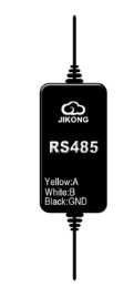
I have seen that Hankzor was also selling a RS485 module? (Pic attached below)
Do you know what is it for and if I need it with the new rev boards?
What you described previously looks as a half duplex RS485 interface header so what is this adapter for then?

I can also see 2 boards but different price, how can I know which one is the latest rev with the LCD header?

and

Appreciate your advise!

A
 

Attachments

  • rs485.jpg
    rs485.jpg
    8 KB · Views: 11
I have seen that Hankzor was also selling a RS485 module? (Pic attached below)
Do you know what is it for and if I need it with the new rev boards?

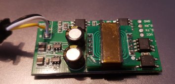
Yes, that module converts the TTL serial uart data to actual RS-485 (A, B, GND lines). You can then use something like this to connect ti to USB:

But as I said, doing this is not needed. Just take the RX,TX and GND pins (and an appropriate JST connector) and hook it up to something like this:
 
Yes, that module converts the TTL serial uart data to actual RS-485 (A, B, GND lines). You can then use something like this to connect ti to USB:

But as I said, doing this is not needed. Just take the RX,TX and GND pins (and an appropriate JST connector) and hook it up to something like this:
I'm puzzled, I have that USB-RS485 converter, can it be connected to the BMS RS485 3-ping port directly? Or can't it?
 
I'm puzzled, I have that USB-RS485 converter, can it be connected to the BMS RS485 3-ping port directly? Or can't it?

No, the BMS output is TTL (TX/RX/GND). You can convert it to USB directly with a TTL to USB converter (sometimes called RS-232 converter, even though this is technically not really correct). The dongle that Hankzor sells turns the TTL signal into RS-485 (A/B/GND) which then gets converted to USB with a USB/RS485 converter.
 
No, the BMS output is TTL (TX/RX/GND). You can convert it to USB directly with a TTL to USB converter (sometimes called RS-232 converter, even though this is technically not really correct). The dongle that Hankzor sells turns the TTL signal into RS-485 (A/B/GND) which then gets converted to USB with a USB/RS485 converter.
Oh, darn it. I figured because it's the 3-pin port RS485, this should work and plug it into the Victron Cerbo...
 

diy solar

diy solar
Back
Top