diy solar

diy solar

Hankzor JK BMS with screen and power button

Yeah, my plan is to just connect two wires to an appropriate 6 pin JST connector and plug that in instead of the display. I'm thinking of not using the display at all at this time.
fantastic work around, very clever! If it goes according to plan i will probably steal your idea ;) haha awesome work. I see your from northern finland. I was in Kuusamo a couple years back, fantastic part of the world! Kippis
 
Kuusamo is nice, Lapland in general is; sadly I don't have much time to go there often. I'll post here when I know for sure the switch thing I mentioned is correct (I mean, I know it is, but I just want to have it as a stand alone switch and have a picture).
 
Update on the power button: for some reason the switch uses the diode of an opto-coupler between between switch and connector. Of course, I've tried just shorting the two switch contacts, and this turns the BMS on as well - but maybe not ideal long term. We could add a diode in the circuit just to mimic the switch in the screen, or put a resistor (1K or something) instead - this should work too. I tried with both a 100K resistor and 1N5819 diode that were on my desk and the BMS turns on in both cases.

The schematic:

Code:
# Display Connector at BMS, R = RED, B = BLACK on the switch cable
┌─────── ─────── ───────┐
│                       │
│ O   O   O   O   O   O │
│ R   B                 │
└───────────────────────┘


 B
 |
 |
 \-->  (button, momentary normal open)
 |
 |
 -
 V  --> diode
---
 |
 |
 R
 
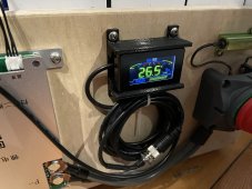
If anyone is interested, I designed a panel mount for the Display that can be 3d Printed. My display came with my JK-B2A8S20P and looks identical to the ones that UpNorth showed pictures of earlier in the thread.

I also discovered that my display will, indeed, turn off the BMS with a long 5(ish) second press of the button.

Model on Thingiverse
https://www.thingiverse.com/thing:5331287

2022-03-26T08:44:04_Davinci_IMG_2114.JPG
 
Quick question: ( If anyone knows) Does this starting issue affect the contactor versions of the JK BMSs or is it restricted to solid-state switching versions?
 
Last edited:
Hey everyone. I have some questions about the JK BMS power consumption. I hope this is the right place to ask:

1) Does someone know the standby power consumption of the JK BMS (with and without screen)?
1a) To disconnect the screen it should be sufficient to disconnect the red (and possibly black) display cable if I understood correctly? Or build a switch into them?
2) Does someone know the "Off" power consumption (switched off via display)?
3) Can I only disconnect the main negative or last (+) balance lead? Or do I need to disconnect all balance leads aswell to truly switch the BMS off?

Background is that I will need to store the battery for around 6 months a year and I hope I can do this without needing to disassemble it to remove the JK BMS.

One thought was to build a main battery switch or breaker between the cells and the JK BMS. But would that be enough to completely switch it off? Or would I have to remove all the balance leads aswell? Is it even save to put a breaker between the battery and BMS? Or may the balance leads only be connected after the main negative is connected already?
 
I've posted screen power consumption numbers of the BMS with screen near the beginning of this thread:

Normal current draw of the BMS itself is something like 560mW if I remember correctly.

You can just switch the B+ line. Some version can also switch off with the button by holding it a few seconds. This also turns the BMS off in the same manner as interrupting B+.
 
That would sum up to about 2kWh per BMS per half a year. My question was if it was possible to build a switch between the Cells and the BMS to disconnect it for storage without needing to disconnect it completely. For external loads, the positive side will be switched and fused aswell, of course. But the intent of my question was if I can also build an easy disconnect for the bms itself.
 
My question was if it was possible to build a switch between the Cells and the BMS to disconnect it for storage without needing to disconnect it completely.

When it's off, it's off and doesn't consume anything. Switch at B+ lead (the one that goes together with the last cell positive) or display button power off (if your BMS supports that).

That would sum up to about 2kWh per BMS per half a year.

That's with the BMS powered on.
 
Ok, so I received my new JK BMS and finished building the 8S pack and its box, so installed the JK this morning. I went ahead and bought it with the display, although I'm not sure if I will use it. I do have a couple of questions / observations:
  • One cell was out of balance when I hooked it up. It was cool to see the active balancing. However, it seems like even with the display disconnected there was some noticeable voltage decrease, even after the balancing had completed. The cells were top balanced a bit over a week ago, and have been sitting idle until I hooked everything up today. In about 3 hours I saw the pack voltage drop from over 27.2V to under 27.1V. I don't think I've seen this on any of my JBD BMS builds. There is nothing external hooked up to the battery. Is this normal?
  • The beep that the BMS does whenever it is booting up or when the Bluetooth connects to it is somewhat unique, but I think I'm getting tired of it. If I want to check the status with the app while everyone else is sleeping in, seems like it would by pretty annoying. Is there a way to turn it off, at least temporarily?
This is for my little 160Ah 24V pack that is mostly to play with, but I may mess with the RS485 port a bit. Has anyone else tried to use the Grafana package that @upnorthandpersonal put together?
 
voltage drop from over 27.2V to under 27.1V

That's a cell drop from 3.4V to 3.3875 - that's pretty normal.

Is there a way to turn it off,

I don't think there is a software feature for this. You could remove it from the PCB, or just cut the traces to the beeper if you're comfortable doing that.
 
That's a cell drop from 3.4V to 3.3875 - that's pretty normal.
Since it apparently isn't self discharge of the cells, I assume you mean this is the expected idle consumption by the BMS. I didn't see any spec for the current consumption on the product page. I guess I could try and measure the current while it is idle. I'm almost certain it must be quite a bit higher than the JBD BMS.

I don't think there is a software feature for this. You could remove it from the PCB, or just cut the traces to the beeper if you're comfortable doing that.
Well, I'm not uncomfortable with doing that, but I wish it was configurable. I'd rather not take the thing apart if I can avoid it. Maybe I'll see if I get used to it. :)

The current bouncing around all over the place is a bit of an annoyance. I assume that it averages out over time, so the Coulomb counting should still be somewhat accurate.
 
Hmmm... Just noticed that the RS485 JST-1.25 connector on the B2A8S20P (8S 200A) is a 3-pin rather than the 4-pin that has been discussed here. The GPS port is 4 pin. Apparently the other models use a 4-pin. I guess I'll need to get some 3-pin if I decide to mess with the RS485. I assume the VBAT pin that @upnorthandpersonal documented on the 4-pin RS485 has been dropped, since only the Rx, Tx, and GND are really necessary.
 
Ok, now I'm confused.

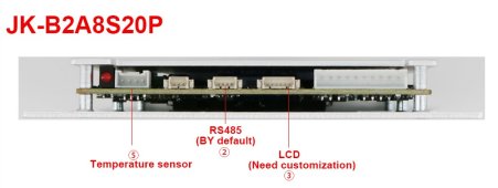
In this post @Nami showed this picture regarding the B2A8S20P that I have. Note that the RS485 is shown as the 4-pin connector, and the 3-pin (to the left of the 4-pin) is not labeled:
Screenshot 2022-04-17 092408.jpg

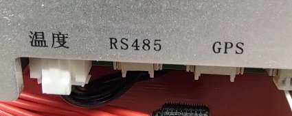
Meanwhile, looking down at the PC board where the connectors are I see this:
IMG_20220417_092757518_HDR.jpg
The temperature sensor is on the left like @Nami said, and the LCD connector is on the far right (mostly off-screen in my pic). But the RS485 is next to the temperature sensor, and is 3-pin. What @Nami says is the RS485 is labeled GPS on mine. Anyone know the truth? @Nami?
 
Since it apparently isn't self discharge of the cells, I assume you mean this is the expected idle consumption by the BMS.

No, more like normal cell voltage settling. Remember, voltage is not an indicator of state of charge for LiFePO4.

I didn't see any spec for the current consumption on the product page. I guess I could try and measure the current while it is idle.

I posted the consumption numbers a few posts ago: 560mW without screen. With screen it's more - see post #34

But the RS485 is next to the temperature sensor, and is 3-pin.

RS485 should be the 4 pin connector.
 
No, more like normal cell voltage settling. Remember, voltage is not an indicator of state of charge for LiFePO4.
Oh I know that voltage doesn't indicate SoC. I think I've told others on this board that fact several times. ;) The only reason I doubted settling is that these cells sat for over a week (10-11 days, I think) and I would have thought they were all settled.
I posted the consumption numbers a few posts ago: 560mW without screen. With screen it's more - see post #34
Argh. Sorry I missed that. Now that I look at it, I remember reading it. My excuse: I turned 64 last month, and there it went....
RS485 should be the 4 pin connector.
Seems odd they would label it for the GPS, and the 3-pin as the RS485. Really though, a TTL UART only needs three, right? I'll give it a try once I get the TTL-serial-to-USB interface board. Thanks for linking to that. See, I don't miss everything!

I know I had a Raspberry Pi board here somewhere, but I can't find it and it was pretty old anyway. This could get expensive, just like everything else in this hobby. :oops:

There are so many revisions of that BMS out there right now that it gets confusing. It should be the 4 pin one. The adapter to RS485 uses 4 pins as well.

I also just started the how-to to get Grafana up and running. I started with a virtual machine, so you could play around with that as well before getting a Pi:


Next entry will be step by step for the Pi. After that there should be a collection of devices and how to talk to them. I don't have a time line though...
 
Well, I think I'm mostly liking the JK BMS.

The "Remaining Capacity" and "Cycle Capacity" items displayed on the App seem to have nothing to do with reality. The manual says something about that the "Battery Capacity" displayed has to be updated after a complete discharge and recharge cycle. I'm hoping they don't mean I would need to take the thing down to 2.5V per cell and back up to 3.65V per cell. Anyone have a better understanding of how to get a more meaningful % SoC, Remaining Capacity, and Cycle Capacity to be displayed?
 
The "Remaining Capacity" and "Cycle Capacity" items displayed on the App seem to have nothing to do with reality.

It takes a cycle for these to be accurate. I don't think you have to be all the way to zero, but you have to hit the steep part of the curve if I remember correctly. I believe you can do this by just charging to full once. It's the same behavior as a Victron smart shunt I think.
 
I just noticed that the Hankzor store on Aliexpress says that the 8S 200A version I bought less than a month ago (JK-B2A8S20P) is no longer available? :oops:

EDIT: Here's the link - https://www.aliexpress.com/item/1005003719328643.html

Anyone know anything about this? Are they just out of stock, or...?

The store's product listings for JK BMS models don't show any 8S models, only >8S that can be used for 8S, probably requiring a buck converter for the BMS power supply.

That didn't last long.
 
I wanted to verify if I ordered the JK-B2A24S20P LCD which is on this page: JK SMART BMS 2A BALANCE CURRENT BMS 200A that I don't need to order anything else from them if I also want to access data from it like @upnorthandpersonal is doing.

You can order the RS485 adapter which you can then connect to a RS485 to USB connector. You don't need this - you can make your own connector to connect directly to the TTL (marked RS485, but it's not) port on the BMS and use a TTL/USB converter instead, but you do need to be able to make the JST connector.
 
I just noticed that the Hankzor store on Aliexpress says that the 8S 200A version I bought less than a month ago (JK-B2A8S20P) is no longer available? :oops:

EDIT: Here's the link - https://www.aliexpress.com/item/1005003719328643.html

Anyone know anything about this? Are they just out of stock, or...?

The store's product listings for JK BMS models don't show any 8S models, only >8S that can be used for 8S, probably requiring a buck converter for the BMS power supply.

That didn't last long.

I was about to order it a few days ago when I saw the same. The support told me it's discontinued because there will be a new version 4S-8S coming in early May. Confirmed by this post: https://diysolarforum.com/threads/jk-4s-200a-bms.38623/
They say it will be more expensive as it also includes a heating function.

I'm debating if wait or buy now from the Minerals supplier which still has it available: https://www.aliexpress.com/item/1005003339311236.html

Edit:
I'm not going to order the RS485 converter since it's not needed and a TTL/USB converter is cheaper. I don't think I'll get the screen either since it consumes too much energy and I don't really need a screen. I'll make the turn-on switch suggested by @upnorthandpersonal here: https://diysolarforum.com/threads/h...een-and-power-button.33267/page-4#post-472658 with the diode, but I'm wondering if that works to turn off as well.
In reality, I won't need to turn it on and off really often so I could disconnect it from the battery when I need to store them for some months before I'm done with the build, but what's the proper way to turn it off? just disconnect the B- lead from the battery?
 
Last edited:

diy solar

diy solar
Back
Top