diy solar

diy solar

Hankzor JK BMS with screen and power button

but I'm wondering if that works to turn off as well.

Not sure - I can't test that since my BMS doesn't support turning off via the button...

but what's the proper way to turn it off?

Disconnecting the balance wires (or just the B+ that's part of the balance leads) works fine. You could put a switch on that B+ lead.
 
Not sure - I can't test that since my BMS doesn't support turning off via the button...


Disconnecting the balance wires (or just the B+ that's part of the balance leads) works fine. You could put a switch on that B+ lead.
Thanks, I guess I'll try the turn-off once I get the BMS.

B+ you mean the first cell B1? Sorry if it's an obvious question, but I've never built a battery before. Having a switch on just one lead would create more resistance on only one wire, doesn't that mess up the balancing accuracy?
Or since you say disconnecting the balance wires, then unplugging the balance harness altogether would be as simple as a switch if that doesn't create problems because all of the wires are removed at the same time.

EDIT:
Sorry, I just noticed the B+ on the schematics, it's a separate lead, the last one, that goes to the last cell positive, so yeah a switch there would make sense. I didn't see that because I was looking at the 8S version schematics which are not as clear as the other versions of the BMS in the official docs.
 
Last edited:
I just got the newest jk bms b2a24s-20p.
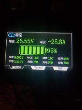
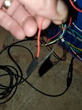
I got the big display with it. So the cord has a small gage red and black loose. Touch them and the bms starts. The screen needs a 12v source. It seems to be our problem coming up with the 12v.
I am running a 8 cell setup so I needed a 24 to 48v converter to power it. Currently I am running the wires for the display across 4 cells. Most of it in not in English. It's almost a waste of money. I asked them about changing the language.
For all you guys having issues getting the app to even see it I had to go to my settings then this bms app and do all the permissions. It never asked me and was not scanning for the bms at all.
I'm glad I've been around stuff like this. It still took a while to dig into the permissions though.
I have it as my main with 3 8cell packs on it
 
Looks like i will be using this BMS, assuming i can order one sometime soon. This will be my first battery build, (24V 1P8S 230ah) so choosing a BMS has been an education... Few decent possible BMS's out there for 200a so JK looks likely. Now with the new heater port for the battery and active balancing this looks like the one. However, im a newbie and ive some questions perhaps some of you fine people might be able to answer please:

I will have a CerboGX and would like communications. This is done through the RS485 port as i gather here, and have looked at the links @upnorthandpersonal posted for adapters, so may i assume this would be the route? What other possibilities for this RS485?

Might i safely assume i can use the HEAT port to control a battery heater? Does the APP support this HEAT function?
Anyone yet utilized this in their battery?

I see the Power Board is the preferred way to activate, i think the display might be redundant for data if available on phone or Cerbo and ive read sometimes they simply don't work. Has anyone come up with any simple activation alternatives? Switch+ 5v power set up? Possible parts list?

Apologies if these questions have been previously answered, i did search.... please refer me links if so.

Thank you! This forum has been EXTREMELY helpful to this beginner.
The display is the big one20220502_182937.jpg
 
Looks like i will be using this BMS, assuming i can order one sometime soon. This will be my first battery build, (24V 1P8S 230ah) so choosing a BMS has been an education... Few decent possible BMS's out there for 200a so JK looks likely. Now with the new heater port for the battery and active balancing this looks like the one. However, im a newbie and ive some questions perhaps some of you fine people might be able to answer please:

I will have a CerboGX and would like communications. This is done through the RS485 port as i gather here, and have looked at the links @upnorthandpersonal posted for adapters, so may i assume this would be the route? What other possibilities for this RS485?

Might i safely assume i can use the HEAT port to control a battery heater? Does the APP support this HEAT function?
Anyone yet utilized this in their battery?

I see the Power Board is the preferred way to activate, i think the display might be redundant for data if available on phone or Cerbo and ive read sometimes they simply don't work. Has anyone come up with any simple activation alternatives? Switch+ 5v power set up? Possible parts list?

Apologies if these questions have been previously answered, i did search.... please refer me links if so.

Thank you! This forum has been EXTREMELY helpful to this
Touch these red and black on the display cable turns it on
 

Attachments

  • 20220502_183154.jpg
    20220502_183154.jpg
    154.3 KB · Views: 59
I will have a CerboGX and would like communications. This is done through the RS485 port as i gather here, and have looked at the links @upnorthandpersonal posted for adapters, so may i assume this would be the route? What other possibilities for this RS485?
I'm pretty sure that the CerboGX will not be able to directly read/understand the data from the JK BMS. There is another project here on the board (https://diysolarforum.com/threads/v...rt-ant-jkbms-heltec-renogy.17847/#post-205916) that has a VenusOS driver that interfaces to the JK BMS (and others). The VenusOS is meant to be a Raspberry Pi image that you can essentially create your own Cerbo GX, and this driver would allow that Raspberry Pi to read the JK BMS. However, the Cerbo GX is a closed proprietary hardware package that I would guess you can't add the driver to. Others here are more expert on the topic, as I have already said more than I am really certain of.... ;)

Might i safely assume i can use the HEAT port to control a battery heater? Does the APP support this HEAT function?
From what I've read about it, this enhancement to the JK BMS uses the low temp cutoff setting to turn on the heat function. Then once the temperature gets above the low temp cutoff it turns off the heat. I would prefer two settings: One where the heat turns on, and one where the BMS cuts off charging. That way I can turn the heat on while the battery is still warm enough that it can take a full charge. The low temp cutoff should be the last-ditch protection of the battery. Having them be the same seems suboptimal to me, but at least it is something.
 
the Cerbo GX is a closed proprietary hardware package that I would guess you can't add the driver to.
Venus OS is what is on the Cerbo GX as well and you can add drivers to it.. You can ssh into the Cerbo GX just like on the Raspberry Pi. The tricky part is to make sure the driver/changes are placed in certain location so that future updates from Victron for the Cerbo GX/Venus OS don't overwrite your changes.
 
I'm pretty sure that the CerboGX will not be able to directly read/understand the data from the JK BMS. There is another project here on the board (https://diysolarforum.com/threads/v...rt-ant-jkbms-heltec-renogy.17847/#post-205916) that has a VenusOS driver that interfaces to the JK BMS (and others). The VenusOS is meant to be a Raspberry Pi image that you can essentially create your own Cerbo GX, and this driver would allow that Raspberry Pi to read the JK BMS. However, the Cerbo GX is a closed proprietary hardware package that I would guess you can't add the driver to. Others here are more expert on the topic, as I have already said more than I am really certain of.... ;)
Here is a link that had me thinking it might be possible with the Cerbo, from DIYbms
. Im intrigued by his approach but since i know pretty much zip/zero about most of this i would leave it to those who do...
 
From what I've read about it, this enhancement to the JK BMS uses the low temp cutoff setting to turn on the heat function. Then once the temperature gets above the low temp cutoff it turns off the heat. I would prefer two settings: One where the heat turns on, and one where the BMS cuts off charging. That way I can turn the heat on while the battery is still warm enough that it can take a full charge. The low temp cutoff should be the last-ditch protection of the battery. Having them be the same seems suboptimal to me, but at least it is something.
I can see your point now. Keeping that low temp cutoff operation would be wise. Well i was designing an auxiliary battery heating system first anyway although was hoping for the "all in one" .... Thanks for your reply
 
Venus OS is what is on the Cerbo GX as well and you can add drivers to it.. You can ssh into the Cerbo GX just like on the Raspberry Pi. The tricky part is to make sure the driver/changes are placed in certain location so that future updates from Victron for the Cerbo GX/Venus OS don't overwrite your changes.
Ive seen videos on doing GUI MODS to the Cerbo,
which cautions regarding the overwrites you've described. I like the mods and was planning on trying them.
 
Venus OS is what is on the Cerbo GX as well and you can add drivers to it.. You can ssh into the Cerbo GX just like on the Raspberry Pi. The tricky part is to make sure the driver/changes are placed in certain location so that future updates from Victron for the Cerbo GX/Venus OS don't overwrite your changes.
Ah, cool. Thanks for clarifying.
 
Keep in mind that the heater function is very new, and I'm not sure if anyone has already tested it. I ordered two extra JK since I wanted to experiment with the display interface and also assumed the heater port would be there - it wasn't. So whatever you do, make sure you specifically mention to the seller that you need those.

As someone else pointed out, the VenusOS drivers are available and they work on the Cerbo GX. If you want more flexibility, a Raspberry Pi with or without VenusOS is a good option as well.
Hi, please send me a message,
I will send you a 4.3 inch display for free.
If you are in the European Union, I need you to pay $1 online and leave your address. I will send you samples using DDP
If you do not belong to the EU, leave your address and I will send you samples using DDP.
Thank you for your support
 
I received my "48V" JK BMS with screen option and was somewhat surprised to see it only using two 7AWG cable? That's 10.6 mm^2 for one so 21.2 mm^2 for the two of them and equivalent to 4AWG. Why does this seem undersized? The ampacity of 4AWG with 90C insulation is 95A.. so to compensate for this the insulation on this cable has a 200C rating on it! Wish would just use larger cable gauge to begin with so the cable won't potentially heat up that much.
 
It doesn't heat up really. Your connectors and lugs will heat up more than the cable, and even then it's minimal. It's also a short cable, which means the resistance isn't very much and power losses are minimal. Now, if these would be a meter long, that would be another thing.

By the way, at 100A this is already 5kW. Do you really plan on pulling the max 200A (10kW) for very long all the time?
No. But I really like what they did with the new 4S version that has the threaded connections so you can use whatever cable size and length you want. The 7AWG is sort of an odd size in the US at least so I'll have to try to use a 6AWG lug and crimp with 8AWG die.
 
That's what I use - 16mm² lugs.
I agree, it is an odd choice. @Nami :)
Maybe we will consider improving this problem. At present, all BMS cable specifications are 7awg, but customers can replace the cable by themselves. For 7awg cable, we can pass the current of 200A in the laboratory
 
Maybe we will consider improving this problem. At present, all BMS cable specifications are 7awg, but customers can replace the cable by themselves. For 7awg cable, we can pass the current of 200A in the laboratory
I just received one of these units with two 7 AWG cables. Technically two 7AWG cables would be rated together to handle around 100Amps. I am sure 200 Amps will work, but did you measure the temperature at 200Amps, and for how long they handled the 200 Amps? They are very short leads, which will help. Two 4AWG cables would be better for these pre-soldered leads given they are so short.

Is there any issues or concerns or watch outs with soldering another AWG4 lead to the unit which would bump the margin at 200 Amps? I am thinking of soldering a 4AWG lead in between the two 7's, and crimping all three into a 1AWG Lug
 
Clarity, those Silicone Wires are rated higher than normal wire... in fact look at the extremely Fine Strand Wire which explains WHY these can handle the output... it is well within spec. Same applies to Corse Copper Wire for battery cables versus Fine Wire Welding Capable which can carry double... And comparing to Solid Wire (like house wire) does not apply at all. DC uses Skin Effect while AC does not. (old dead horse, not bringing that back to life, too many love to argue nonsense over that).

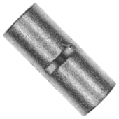
Edit: I am converting my "fleet" to JKBMS. They are all identical with paired 7AWG Silicone Wire for each side. As teh wires are too short for my particular implementation, I connected both 7-AWG together (per side) with a 4-AWG Butt Connector and 4-AWG Silicone Wire as the extension. Hydraulic Crimper used and the connections are perfect, zero issues. NOTE: Not all Butt Connectors will do ! You require a MINIMUM of 10mm, The Linked Butt Connectors below provide for 13mm (1/2") to be inserted on each side with a Dead-Stop in the center to make sure equality on both sides. These also have "grabbers" inside the connector which really locks them in-place. NB: Many Butt Connectors are "short" and few have the grabbers as well. Crimp 4-AWG with 25mm Die.

1653501763349.png
 
Last edited:

diy solar

diy solar
Back
Top