diy solar

diy solar

kWh vs. discharge rate

SeaGal

Photon Sorceress
Joined
Aug 17, 2022
Messages
2,642
Location
UK
Am trying to get my head around any impact on the total energy that can be usefully extracted from an LFP battery rack if one increases the instantaneous maximum discharge rate, but whilst still consuming the same amount of energy over a given time period.

Or, to put it a bit clearer with an example; if one was to discharge say a 280Ah / 14.3kWh battery, via an inverter, with a load of 2kW for an hour and then, afterwards, a 3kW load for an hour, would that result in the batteries being depleted faster than running both loads in parallel at a rate of 5kW. i.e. is it better to (say) cook and do washing in series or parallel with everything else equal?

Obviously the Ah rating of the battery is constant, but the Wh rating is dependent on voltage as well as current. And drawing a larger load will result in more current being drawn whilst simultaneously decreasing the voltage of the cells. In addition to that, internal resistance of the cells and the resistance of the d.c. cable between battery and inverter will cause more heat to be generated = lost energy (well not really really lost, just converted into energy that is not useful to me). But that extra heat is for less time.

What I've hit a mental block on is whether "5kWh used for 1 hour + 1 hour with inverter idle" would result in more, less or the same energy consumed from the batteries compared to using 5kWh over 2 hours?
 
Battery capacity is measured at a specific C rate (discharge rate) which is a fraction or multiple of the capacity. The answer to your question depends on the design of your battery. Do you have a spec sheet with your C for that battery? It's usually 0.5 or 1.0 but it can technically be anything
 
All batteries have overpotential (polarization) voltage overhead loss required to drive the kinetic/chemical process to produce cell output current. In addition, there is IR loss associated with connections.

Overpotential for given cell load current depends on condition of cell, and temperature. LFP get worse at colder temps below about 15 degs C.

The greater the load current the greater the cell terminal voltage slump.

A 280 AH LFP at 50% state of charge will have a rested open circuit voltage of close to 3.300vdc.

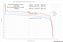
If you draw about 2kW for a 16s series pack that will be about 38.5 amps with each cell slumping from 3.300v to about 3.250 vdc. 50 mvdc x 38.5 amps = 1.9 watts of loss in each cell. For 16s battery that is 30.75 watts loss. This does not include any additional losses due to terminal to bus bar connection, bus bar resistance, or cabling resistance.

If you draw about 3kW for a 16s series pack that will be about 57.9 amps with each cell slumping from 3.300v to about 3.235 vdc. 65 mvdc x 57.9 amps = 3.75 watts of loss in each cell. For 16s battery that is 60.23 watts loss. Additional IR losses at the greater load current for terminals, bus bars, and cabling will be greater.

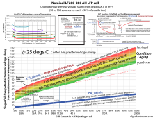
As cells age, their condition degrades. Over the life of cell the overpotential can increase 3-5 times its new condition value.

EVE LF280K 40A charge_discharge curves.png
LF280 overpotiential curve.png
 
Last edited:
Battery capacity is measured at a specific C rate (discharge rate) which is a fraction or multiple of the capacity. The answer to your question depends on the design of your battery. Do you have a spec sheet with your C for that battery? It's usually 0.5 or 1.0 but it can technically be anything
I'm using EVE LF280K cells. They can handle 1C discharge, but inverter & BMS will only draw 100A max, so 0.35C max.

Not sure at what C rating, the LF280K's are measured for capacity though.
 
If you draw about 2kW for a 16s series pack that will be about 38.5 amps with each cell slumping from 3.300v to about 3.250 vdc. 50 mvdc x 38.5 amps = 1.9 watts of loss in each cell. For 16s battery that is 30.75 watts loss. This does not include any additional losses due to terminal to bus bar connection, bus bar resistance, or cabling resistance.

If you draw about 3kW for a 16s series pack that will be about 57.9 amps with each cell slumping from 3.300v to about 3.235 vdc. 65 mvdc x 57.9 amps = 3.75 watts of loss in each cell. For 16s battery that is 60.23 watts loss. Additional IR losses at the greater load current for terminals, bus bars, and cabling will be greater.
Great thanks... useful numbers there!

And that all makes sense because the losses are non-linear, due to the voltage drop, then one is better off running loads in series, rather than parallel to reduce the losses (y)
 
If you draw about 2kW for a 16s series pack that will be about 38.5 amps with each cell slumping from 3.300v to about 3.250 vdc. 50 mvdc x 38.5 amps = 1.9 watts of loss in each cell. For 16s battery that is 30.75 watts loss. This does not include any additional losses due to terminal to bus bar connection, bus bar resistance, or cabling resistance.

If you draw about 3kW for a 16s series pack that will be about 57.9 amps with each cell slumping from 3.300v to about 3.235 vdc. 65 mvdc x 57.9 amps = 3.75 watts of loss in each cell. For 16s battery that is 60.23 watts loss. Additional IR losses at the greater load current for terminals, bus bars, and cabling will be greater.

I have been curious about how the rise of internal battery temperature changes the kWh capacity of a cell. As you show, we loose energy in the form of voltage slump/internal battery heating. My question is, don't we gain available energy in the battery as it warms? Just like how a cold soaked cell has less available energy than a room temperature cell.
 
Heat has a direct relationship to kw usage. Any heat generated will reduce overall capacity for use energy.
Heat is the enemy!
 
My question is, don't we gain available energy in the battery as it warms?
It does improve but it is just a small amount compared to the reduction at cold temperatures.

You can get an idea from the cell impedance vs temp graph at the upper left hand corner of last insert picture. Between 25 degs C and 50 degs C the overpotential only drops about 25-30% but from 25 degs C to 0 degs C it rises a bit over 200%.

Lithium-ion migration through electrolyte gets sluggish in cold electrolyte. You need higher overpotential to 'kick them in the butt harder' to get them to move along to meet the demanded cell terminal current.

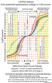
Overpotential follows a logarithmic curve, but depending on electrode thickness design, another factor kicks in called layer ion migration starvation. For 280AH 'blue' cells, they are thick electrode cells with the most AH capacity put into given cell volume but do not support high C rate discharge as well. They start to suffer layer ion-starvation above about 0.5 C(A) current caused by their thick electrodes and the longer ion migration path in electrolyte soaking around the electrode granules. (graphite for neg anode, LFP for pos cathode). This ion migration starvation increases the overpotential voltage slump at higher cell current above the logarithmic relationship.

Electrolyte wants to stay charge neutral. High overpotential caused by high cell current demand creates voltage gradient through electrolyte which opens electrolyte up to greater decomposition degradation.

LFP overpotential is fairly symmetrical for charging and discharging current direction through cell.

LFP Over-potential Chart.png

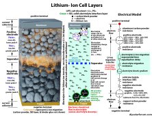
Li-Ion Graphite battery model.jpg
 
Last edited:
It does improve but it is just a small amount compared to the reduction at cold temperatures.

You can get an idea from the cell impedance vs temp graph at the upper left hand corner of last insert picture. Between 25 degs C and 50 degs C the overpotential only drops about 25-30% but from 25 degs C to 0 degs C it rises a bit over 200%.
Interesting. Thank you for the explanation.

When I look at this chart, it looks more like this: from 0 deg C to 25 deg C, decrease of internal resistance by about 110%. From 25 deg C to 50 deg C, decrease of internal resistance by about 40%. Also the temp conversion for 50 deg C line is incorrect I believe.

So it seems that a certain amount of internal heating can be beneficial, depending on starting temp. From a conservation of energy point of view, I would think that heating the cell with a resistance heater powered by cell would be equivalent to letting the cell self heat through internal resistance, but maybe it is not this simple...
 
I'm using EVE LF280K cells. They can handle 1C discharge, but inverter & BMS will only draw 100A max, so 0.35C max.

Not sure at what C rating, the LF280K's are measured for capacity though.

How do you do the math to calculate 100a draw being .35C of a 280ah battery? Is there a calculator y’all use or just a basic equation or is it different based on the product insert for the cells
 
How do you do the math to calculate 100a draw being .35C of a 280ah battery? Is there a calculator y’all use or just a basic equation or is it different based on the product insert for the cells
1C = 280 amps, so 100 amps = 100/280 = 0.35714C.
 
Too much cell heating accelerates parasitic undesired chemical reactions that damages cell primary operation. Not exclusively, but dominantly, effects electrolyte decomposition.

Electrons escaping electrodes damages electrolyte. The SEI protective shell around graphite which restricts electrons from escaping graphite is damaged as graphite expands and contracts during cycling. SEI protective layer is regrown during subsequent recharging, but the regrowth consumes some electrolyte and free lithium reducing cell capacity and increasing cell impedance over life of cell. It is unavoidable normal aging process.
 
Not sure at what C rating, the LF280K's are measured for capacity though.
0.2 C rate, at a specified temp, IIRC 25-degC

And that all makes sense because the losses are non-linear, due to the voltage drop, then one is better off running loads in series, rather than parallel to reduce the losses (y)
In addition to the losses the battery will experience, I notice (with my inverters) the inverter self consumption is also non-linear, such that larger loads consume more energy, compared with lower lower loads run longer duration.

Running loads in parallel can be the best option under certain conditions: ie if the ESS is near capacity and solar potential is available to supply the high load, but not for the duration if the loads are run in series.
 
Back
Top