diy solar

diy solar

LFP from Docan failed + the warranty experience

1) Looking at the pictures, I cannot tell how all the 16 cells are connected and you only have one BMS. I do not see any cells connected in parallel to get 8s2p. I see top row cells are connected in series, same for the bottom row so I cannot see how you use one BMS for two 8s-cell configuration.
2) The BMS (21s) is rated at 3.7V for Li-ion, not for 3.2V LiFePO4. Can it be configured for LiFePO4? And are you wiring the BMS as 8s?
3) The way you are using the battery busbar for connections, it does not look good, not much clearance.
4) What are those 50A fuses on the cell terminals for?
5) You you draw out the wiring diagram of your battery?

1677358656189.png
1677362867852.png

1677360003861.png

1677360233759.png
 
Last edited:
pics showing BMS wiring, taken early Feb,
IMG_20230201_182819.jpg

What are all those thin wires connected to one battery terminal doing?


Those lugs on the BMS look dangerously close to shorting to me.
 
I see what I think are 2 bluetooth modules which means there may be 2 bms modules. I also see 2 bms heatsinks.

. I see cell c4 is connected incorrectly but I assume because your started disecting the pack.. I will stand by my statement that if any component failed here to bring all those cells down the way they did it would have to have been something other than all the cells like the BMS, and why are these 3.7v nmc bms and not the correct 3.2 lifepo4 version?
 
Last edited:
What are all those thin wires connected to one battery terminal doing?
That's how those BMS's are wired, you jumper wire together depending on how many cells you are running; they can run 7s-21s.
I'm running 2 similar JBD BMS's and 32 230ah cells from Jenny @ Docan.
They are all performing great.
You can see mine in the attached photos.
 

Attachments

  • IMG_20221024_194300.jpg
    IMG_20221024_194300.jpg
    113.6 KB · Views: 31
  • IMG_20221024_194454.jpg
    IMG_20221024_194454.jpg
    393 KB · Views: 31
I'm even more confused, all those jumble of wires connected to 1 cell, if you needed 8s why not just order the JBD 8s BMS. Not many have experience with the BMS you are using looks like there will be trial and error to find the issue.

IF the wires are indeed correct, then you have 1 dead cell and 1 basically terminally ill (the 1.99).

I doubt Docan is going to warranty because this may have been a BMS issue.
My guess is because a bms designed for 6 to 21 cells is more flexible... Most of the bms I have seen can be used for a range of cells successfully.. The 300amp JBD im running in my golf cart is good for 7-20s and I run 16 this way with no issues. If I choose to up the voltage of my pack in my cart this bms will support it. In the golf cart world a brand of drop in lithium batteries uses these bms called Roy Pow.. Of course they do use the Lifepo4 version and not the 3.7v lithium ion version.
 
1) Looking at the pictures, I cannot tell how all the 16 cells are connected and you only have one BMS. I do not see any cells connected in parallel to get 8s2p. I see top row cells are connected in series, same for the bottom row so I cannot see how you use one BMS for two 8s-cell configuration.
2) The BMS (21s) is rated at 3.7V for Li-ion, not for 3.2V LiFePO4. Can it be configured for LiFePO4? And are you wiring the BMS as 8s?
3) The way you are using the battery busbar for connections, it does not look good, not much clearance.
4) What are those 50A fuses on the cell terminals for?
5) You you draw out the wiring diagram of your battery?

Thank you Bud Martin, et al. for the feedback :)

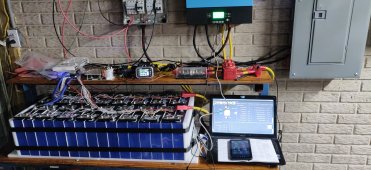
We have considered all the points. We have no short circuit concerns – I know you cannot see the situation clearly from 2D photos.

1) As I said earlier, we have 8S + 2 x 4S, we are in a transition to 2 x 8S. That’s why we were using 3 BMSs.

2) Wow, thank you for noticing this. We didn’t. I double-checked my BMS order and confirmed that we ordered the LiFePO4 version correctly, but JBD sent us the wrong version -- model # and part # are the same -- that’s crazy! We did try to configure some parameters differently using Overkill app because the BMS manual says the BMS was made for ternary (Li-ion) cells. We are not aware if a separate manual exists for two versions. We made parameter changes before starting to use the BMS. We may or may not have changed everything we needed to change for LiFePO4. Looking from the outside, the LiFePO4 and Li-ion versions are identical. May attach a photo when I get a chance later. We will be busy dismantling the battery, etc.
Will contact JBD, and see what they say.

4) It’s actually 250A MRBF.

We will now turn our attention to learning how to top balance as it would be our first time. Then seeing how many cells we can salvage.
 
We will now turn our attention to learning how to top balance as it would be our first time. Then seeing how many cells we can salvage.
There's a whole write-up in the Resources section that can take you through it step by step. What many of us have done is to assemble the pack into a battery from the start, throw it on a bog standard high amp charger and do a full charge. Once it thinks it's charged THEN tear the pack apart, set up the cells in parallel, and top balance from there. That makes the process go MUCH faster, and it's a pretty long process.
 
We have 16 cells (8S + 2 x 4S) which were not top balanced prior to use. We plan to work first with the 24V cells (injured). This way we can make use of the 12V batteries to operate our 12V appliances while we try to revive the injured cells. Once we had a practice run with the injured cells, then we may attempt to top balance the 12V battery cells, assuming that is recommended.


When I top balance these injured cells, in which way should I balance differently compared with when you are balancing a new set of healthy cells? We read a good pdf from here: https://diysolarforum.com/resources...ls-using-a-low-cost-benchtop-power-supply.65/ I would like to know how to tweak the procedure for injured cells.

I found this post (https://diysolarforum.com/threads/strange-issue-with-48v-lifepo4-system.49308/page-2#post-628805). I also found a YouTuber charging at 0.1A or something, so we hope starting to charge at 10A is ok in our case.

This is our plan: Using an example of the voltages from the time we took a video:
2.664V
2.625
1.921
0.660 – will not attempt.
2.649
2.652
2.660
2.728
We will start charging the second lowest voltage cell (1.921V) first at 3.000V and 10A to bring it up to the highest voltage (2.728V) of the pack. Repeat the process to make all cells ~ 2.728V.
Then connect the 7 cells in series and charge at 21V (3V x 7) and 10A, with a 6-21S LiFePO4 BMS. Gradually increase the voltage by 0.7V (0.1V x 7) , up to 25.2V (3.6V x 7). When the voltage reaches the minimum for balancing to turn on (3.350V per cell min., per the 4s manual), the BMS will automate the balancing process.

1) I think the instructions from Steve S (see the second link above) introduce connecting cells & BMS much later. Let me know if my plan sounds safe enough.

2) Does anyone know of other step-by-step instructions (links / videos) to revive injured cells?

Thanks.
 
These 280Ks ...
Hi Alkaline,
I’ve read your post here,
https://diysolarforum.com/threads/easy-way-to-read-eve-date-codes.41991/
and here
https://diysolarforum.com/threads/disappointing-eve-280k-results.47555/post-604445

I did a quick look. My worst 2 cells’ date code show July 2021. (S/N starts with B7)

Other cells seem to be from April (B4) or May (B5) 2021. According to your comments, these may have a smaller chance of being defective.

If I were to replace the 2 cells, do I need to search older 280K cells, e.g. from April or May 2021?
 
Last edited:
Try to get cells as close to the date as you can, but quite honestly get whatever you have access to. Be careful make sure you do not end up with 280N cells, those have terminals that are closer and have a different chemistry than the 280K.
 
@princesse with cell voltages showing in your BMS app as around 3.20-3.21V I am sure your battery was not at 60% SOC, even the SOC meter built into the app said that. On my LiFePO4 battery such voltages (with zero load current) correspond to around 20% SOC and are the point where the voltages start to decline more steeply.

If your BMS is a Li-Ion version and not LiFePO4 it may explain why the SOC indication is misleading.

It seems pretty clear your pack was out of balance and your BMS failed to protect the cells from over discharging. It’s nothing you can or should claim warranty on from Docan.
 
Good luck with a warranty claim from Docan
I emailed with Amy last night, I have a JBD 200 amp 48 volt BMS that has a intermittent 2.5 voltage drop across the solenoid
Causing my Radian inverter to charge every day when it doesn't need too.
She told me to send her a video and she would send it to JBD.
Today it happened at 4:08 AM, a little hard to catch on video
There was no promise to replace it, just that she would send the video to JBD
Doesn't seem like they want to honor any warranty without jumping through a lot of hoops
 
I have a Kaiweets HT206D digital multimeter and a Wanptek 10A power supply DPS3010U. I don’t have a capacity meter. How can I get a sense of capacity or cell health?

E.g. after a cell is topped to 3.227V by the power supply, I left the cell not charged for almost 36 hours. The voltage dropped by 0.014V to 3.213V. Is this any indication of the state of health?

My injured cells (7 cells in parallel, which once were between 1.921V and 2.728V each) are now having difficulty reaching 3.4V. Currently the power supply is set at 3.40V, 10A, CV, the actual current is ~4.8A, cycling up and down, but was averaging verrry slowly down. The cell that was once 1.921V was removed today because the low point in the charge pulse cycle was going up instead of down.

What's the minimum voltage a cell should maintain after x hours of rest after a charge, to be useful as a part of 24V battery? (We have 8 other cells to become a 24V battery, used in parallel, with the injured set.)

Thanks.
 
Removing the 1.921V cell did not improve the situation, i.e., the low point in the charge pulse cycle is still going up.

Would I need to charge fewer # of cells? (Currently 6 cells in parallel).
 
Back
Top