diy solar

diy solar

LFP full charge @ 3.4V/cell

sunshine_eggo

Happy Breffast!
Joined
Oct 26, 2021
Messages
15,953
Location
HBR, USA (6500' in ENE AZ)
Thought I'd try a little something on a cheap 12V I've been testing...

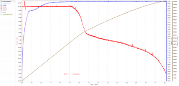
Charge to 20A @ 13.6V (3.4V/cell), 2A tail current.

When testing at cell level and dealing with testers that don't have separate sense leads, lead resistance plays a big role, and I would typically observe cells get charged to about 95% SoC @ 3.4V.

Here's a plot of the charge:
1707709263845.png

0.2C charge
2.5 hour bulk
5 hour absorption
0.02C tail current
104.6Ah input (tested at 105.5Ah)

Have about a 0.12V drop in the leads @ 30A, so it's pretty negligible at 2A.

With sense leads, it would have spent more time in bulk, but not a lot.

Subsequent charges:

3.45V/cell, 0.1C with 0.01C tail current: 0.5Ah input
3.50V/cell, 0.05C with 0.005C tail current: 0.2Ah input

Very little added, and one could argue the low tail currents at these voltage levels indicate full charge or even slight overcharge.

No way to monitor individual cells.

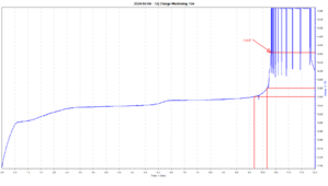
For comparison, this was the voltage log of a 10A charge to 15.6V (was counting on BMS cut-off):
1707710122970.png

This was done with a 30V/10A supply. I didn't want to risk my charger reacting badly to BMS cut-off when I know the power supply can take it. With only a few brief exceptions the power supply output 10A the whole time, so the time scale is equivalent to time * 10Ah capacity and represents a 0.1C charge and tail current.

At 9.7 hours, 13.6V, 97Ah input.
At 10.2 hours, 13.8V, 102Ah input.
etc.

The last 1.5 hours was the BMS coming out of protection and briefly charging again before re-engaging protection.
 
That’s a good test to demonstrate that a LiFePO4 cell can be fully charged at a much lower voltage than 3.65V.

If you have a system with no residual loads, it pays to turn off the charge controller altogether when “fully charged”.
 
That’s a good test to demonstrate that a LiFePO4 cell can be fully charged at a much lower voltage than 3.65V.

If you have a system with no residual loads, it pays to turn off the charge controller altogether when “fully charged”.
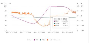
Yes, I have mine set to charge my packs to 54.5V which is 3.4V per cell.

Charging.jpg
 
Last edited:
Thought I'd try a little something on a cheap 12V I've been testing...

Charge to 20A @ 13.6V (3.4V/cell), 2A tail current.

When testing at cell level and dealing with testers that don't have separate sense leads, lead resistance plays a big role, and I would typically observe cells get charged to about 95% SoC @ 3.4V.

Here's a plot of the charge:

View attachment 194954

0.2C charge
2.5 hour bulk
5 hour absorption
0.02C tail current
104.6Ah input (tested at 105.5Ah)

Have about a 0.12V drop in the leads @ 30A, so it's pretty negligible at 2A.

With sense leads, it would have spent more time in bulk, but not a lot.

Subsequent charges:

3.45V/cell, 0.1C with 0.01C tail current: 0.5Ah input
3.50V/cell, 0.05C with 0.005C tail current: 0.2Ah input

Very little added, and one could argue the low tail currents at these voltage levels indicate full charge or even slight overcharge.

No way to monitor individual cells.

For comparison, this was the voltage log of a 10A charge to 15.6V (was counting on BMS cut-off):

View attachment 194956

This was done with a 30V/10A supply. I didn't want to risk my charger reacting badly to BMS cut-off when I know the power supply can take it. With only a few brief exceptions the power supply output 10A the whole time, so the time scale is equivalent to time * 10Ah capacity and represents a 0.1C charge and tail current.

At 9.7 hours, 13.6V, 97Ah input.
At 10.2 hours, 13.8V, 102Ah input.
etc.

The last 1.5 hours was the BMS coming out of protection and briefly charging again before re-engaging protection.
One thing that I don't get is how would you get to a 100% in the real world using PV with an Absorption time that long? Your switching from Bulk charge at about 48% SOC.
 
One thing that I don't get is how would you get to a 100% in the real world using PV with an Absorption time that long? Your switching from Bulk charge at about 48% SOC.

I would simply tell my MPPT to run a fixed absorption time of 5 hours, or a tail current of 2A. On good days, I'd easily get there, but that is the trade-off.
 
Science?
I don’t know that anyone’s saying to actually only charge your cells to 3.4V. But it’s good to know that if you did 3.45V or 3.5V, you’re still going to get full usable capacity.

I might be misreading here but rested fully charged cells are like 3.365 or something.

So yeah, getting the cell to 3.4 or 3.45 means means it's fully charged.
 
I might be misreading here but rested fully charged cells are like 3.365 or something.

So yeah, getting the cell to 3.4 or 3.45 means means it's fully charged.
But this isn’t rested, it’s charging. If you look at the first graph, the cell gets to 3.4V at the 2.5 hour mark, but continues to charge for about 5 more hours.
It’s not immediately fully charged at 3.4V, but it does get there eventually.
 
But this isn’t rested, it’s charging. If you look at the first graph, the cell gets to 3.4V at the 2.5 hour mark, but continues to charge for about 5 more hours.
It’s not immediately fully charged at 3.4V, but it does get there eventually.

Understood.

I'm just trying to understand why it's important.
 
What's the point though?

Why charge it up that slow?
The point is that if you have a battery connected to a charge controller set at 3.40V and you have no significant load (eg off-grid house when you are on holiday, or boat on shore charge while docked) you will fully charge the cells and begin lithium plating.
 
The point is that if you have a battery connected to a charge controller set at 3.40V and you have no significant load (eg off-grid house when you are on holiday, or boat on shore charge while docked) you will fully charge the cells and begin lithium plating.

Ah. This will be my situation for much of march-october.
 
Back
Top