diy solar

diy solar

LiFePO4 Battery wiring... parallel or busbar?

chateau_nomad

New Member
Joined
Jun 22, 2023
Messages
34
Location
Lancaster
I currently have two 100Ah SOK batteries in a parallel string, with all exactly equal length cables. The second battery positive post has a class T 300A fuse, then is connected to a Lynx Power In busbar adapted to accept MEGA fuses. I have a QWORK shunt attached to the negative post (between second battery and Lynx Power In).

The issue so far (after one season) is the Bluetooth BMS readings from each individual battery vary wildly as though not balanced. I have COMPLETELY discharged each battery separately to BMS cutoff... then recharged completely. After a while, they're out of whack again. However, the QWORK monitor will display 100%.

I'm preparing to add an additional (3rd) matching SOK 100Ah battery. So...

Would rewiring the battery bank to a separate bus make any difference? As in... instead of cabling the batteries TOGETHER in a parallel "string", run equal length cables from each individual battery to positive and negative busbars? Then a single run from the busbars to the Lynx Power In.

Question is... would adding this additional busbar between the battery bank and Lynx Power In do anything to help keep the batteries in balance? Or a waste of time? Suggestions?
 
I thought the cells won't balance unless you're full for x hours.

With 2 batteries I always feel it's better to have positive come off one and negative off the other, 3 I'd do the same. The only concern is you're pulling 2-3x the power through the leads in the battery, so they need to hold the load
 
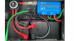
This is how I hooked up my two SOK 208Ah 12V batts. I don't have BT BMS's. I installed one and it cuts off at 122A. My non BT bms is good for 155A+. With the Victron MPII 3000kVA inverter, I have seen 325A. But I have no idea what is happening at the cell level :(
DC wiring 290RL rev 1 install.jpg

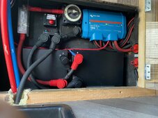
I originally had them hooked up with the criss cross apple sauce method but decided I didn't like that. Forget why, but I like the current hookup better.
IMG_5079.jpg
 
Last edited:
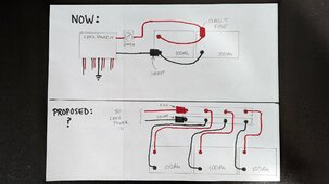
This is a diagram of what I have now vs changes... adding busbar connections before the Lynx. Comments/suggestions welcome!
Battery diagram.jpg
 
I like the bus bar. You could go crazy and use a Lynx distributor with fuses and fuse each battery individually. I didn't do that. The T400 fuse is close enough to protect all the 4/0 wires.
 
Bluetooth BMS readings from each individual battery vary wildly
Thus is due to issues with the BMS computing state of charge. You don't have a balance problem , just faulty reporting via the app.
Dont waste too much time with cables and buss bars, it won't make any difference.

Looking over your previous posts it seems the battery monitor is giving incorrect readings , perhaps due to incorrect setup.
 
Thus is due to issues with the BMS computing state of charge. You don't have a balance problem , just faulty reporting via the app.
Dont waste too much time with cables and buss bars, it won't make any difference.
The "easy" way for me to add the third battery would be just extending the parallel "chain"... which is the way I've often seen it done with FLA battery banks. BUT - this is LiFePO4 and I wasn't sure about screwing up the cell balance. I've read before that SOK's BMS does a less than stellar job of tracking/reporting. Have you heard of any long term effects with just ignoring the BMS readings and use the shunt's calculations? I've read in forums where it's stated to just use the batteries and the charge/discharge cycles will eventually even out.
 
I like the bus bar. You could go crazy and use a Lynx distributor with fuses and fuse each battery individually. I didn't do that. The T400 fuse is close enough to protect all the 4/0 wires.
The busbars add some additional work and hardware... and I like the aesthetics of organizing. BUT - If it's a waste of time/effort/cash I'd just as soon add the third battery using the same cabling sequence I used in the two battery setup. My real concern is "indicated" battery charge/balance as reported by the SOK BMS and whether I should be losing sleep over something that might be a non-issue??
 
I like to wire them as:

(battery 1 ) --- ( breaker ) --- ( bus bar)

( battery 2 ) ---- ( breaker ) --- ( bus bar)

( battery 3 ) --- ( breaker ) --- ( bus bar)

( fuse block ) --- ( breaker ) ---- ( bus bar )

etc.

This makes it easy to isolate off various portions of your system to do misc changes and repairs. Imagine the situation where you are on a trip and something is not quite right - a flip of a breaker and the issue can be dealt with later.

It also allows for an easy way to isolate off an individual battery to reset the BMS in case it trips. The alternative is to get out the tools and disconnect them one at a time. Maybe you can do it, but can your other family members ?

There also are situation where having all of the current flowing through the "end" battery terminal can cause it to over heat. This setup makes that very unlikely.

This can work for 12, 24 or 48 volt systems, assuming that you use the right breaker.
 
Last edited:
I am not quite sure why your readings are off, but the SOC meters that I am familiar with, they work by counting "down" from full.

So imagine starting with a full tank of gas and then pushing a button that tells the meter - "it is full"

The meter then measures how much gas is going in and out - based on the original "it is full" setting.

I have only used the battleborn LiFe and Lifeline AGMs so far and they seem to really stay well balanced battery to battery, even in series.
 
Last edited:
Back
Top