diy solar

diy solar

Lifepo4 bow thruster batteries, which BMS?

greyghost

New Member
Joined
Feb 23, 2020
Messages
40
I’m considering swapping out my two 12V 100Ah AGM bow thruster/anchor windlass batteries for Will's current favorite, Fortune 60A cells. Probably 16 cells in either individual 4S or 2P4S configuration. All loads 12V.

The thruster draws 4300W/12V = 360A and the windlass 1700W/12V = 142A for a total draw of some 500A on a short-term basis. Add for inefficiencies. The thruster is typically used momentarily while docking. However, the motor can run continuously for a maximum of 7.5 minutes before shutting itself down for cooling. At this time, the thruster will have withdrawn 360A(7.5/60)h = 45Ah from the battery bank. The windlass is typically used for a longer period of time raising the anchor, say 5-10 minutes. In this case, 142A(10/60)h = 24Ah.

Nominal capacity of sixteen 60Ah Fortune cells in a 12V environment is 240Ah. Max continuous discharge current is 720A. I note that I will exceed the 1/3C optimal discharge rate while using the thruster. I also note that with these cells I may have to double up on the 150A rated bus bars.

Config 1: 2 batteries in a 2P4S configuration would require one BMS for each battery capable of 250A at minimum.
Config 2: 4 batteries in a 4S configuration would require one BMS for each battery capable of 125A at minimum.

Which BMS would you recommend for each of these configurations? Low temp cut-off nice but not hugely important. I would prefer not to install external contactors. As always, add for overhead, losses and false advertising.

I welcome any responses, comments, etc.

Cheers,
Doug
 
Some unorganized thoughts...

  • Fortune cells have great connections but are large for their capacity. You could (likely) fit 4 of the Xuba 180ah cells in a group 31 battery box. A better investment may be beefing your entire house bank to LifePo4; I'd guess that you have the appropriate wires already run and compared to fortune you can get double capacity for the same price.

  • Your listed amp ratings are for a stalled condition. You wouldn't see these on a regular basis. If you have a shunt you can test with a multi-meter or oscilloscope to monitor the spikes and calculate the current draw.

  • Unless your seamanship is terrible, consider that you won't use your bow thruster and windlass together; therefore max current in a stalled condition 360A - size for this and/or what the thruster manual says.

  • You won't find a BMS that can support the load ... you'll need a relay. Back to considering a house bank upgrade, you could parallel cells behind a 120-200amp BMS for your panel and connect the thruster/windlass via a relay with appropriate fuses... Wire it to turn on/off automatically and ensure the BMS could over ride in a LVD scenario.

  • You likely run the engine when using these, so the alternator will share the load if connected to the LiFepo4 bank .

  • Your amp figures are at 12v which is dead battery and worst-case scenario; current draw will drop as voltage increases.
 
Last edited:
Some unorganized responses...

But first, a bigger picture. The boat currently has 12 AGMs aboard: 7x120Ah deep cycle for the house bank, 2x100Ah starting battery pairs each for bow and stern thruster, and a single 180Ah engine start battery. Power supplied by 180Ah alternator, 1200W solar array. All Victron equipment aboard, MPPT, 2 MultiPlus 3000, BMV, etc. Long term, I expect I'll end up with LFP for all but the AGM engine start battery. I'm thinking I'll start with the bow thruster to lose weight in the bow.
  • Fortune cells have great connections but are large for their capacity. You could (likely) fit 4 of the Xuba 180ah cells in a group 31 battery box. A better investment may be beefing your entire house bank to LifePo4; I'd guess that you have the appropriate wires already run and compared to fortune you can get double capacity for the same price.
Size is not a big concern here. I currently have enough space in either of the two battery boxes serving the bow thruster for two 4S 100Ah Fortune cell batteries, or similar. Yes, appropriate wires already run. Using the house bank to supply thruster loads is possible, but I'd say there's 10 feet between the house bank and the bow thruster (more to the aft thruster), so RT is 20 feet vs maybe 4 feet RT now. Cables would have to be very big to provide proper voltage at the bow (or stern) thruster for operation using the house bank.
  • Your listed amp ratings are for a stalled condition. You wouldn't see these on a regular basis. If you have a shunt you can test with a multi-meter or oscilloscope to monitor the spikes and calculate the current draw.
True.
  • Unless your seamanship is terrible, consider that you won't use your bow thruster and windlass together; therefore max current in a stalled condition 360A - size for this and/or what the thruster manual says.
My seamanship aside :) , 360A seems a reasonable number to use.
  • You won't find a BMS that can support the load ... you'll need a relay. Back to considering a house bank upgrade, you could parallel cells behind a 120-200amp BMS for your panel and connect the thruster/windlass via a relay with appropriate fuses... Wire it to turn on/off automatically and ensure the BMS could over ride in a LVD scenario.
Agreed, might need a relay here in the end, but would prefer some installation simplicity.
  • You likely run the engine when using these, so the alternator will share the load if connected to the LiFepo4 bank .
True.
  • Your amp figures are at 12v which is dead battery and worst-case scenario; current draw will drop as voltage increases.
True enough. If we agree to use 360A, then: 2 100A (or larger) batteries in parallel, 4S configuration, each with a 200A BMS, this might work. Not a lot left for overhead, and I would have to locate a 200A BMS that could actually carry that load reliably. Low temp cut-off not critical, high temp is. Any thoughts on such a critter?

Cheers,
Doug
 
what kind of boat? single alternator?

I think the best method of attack would be to map out a holistic view of your electrical system... you don't want to piecemeal it.

Maybe consider 24volt for the thrusters, windlass, etc. on their own bank & alternator - many convert easily and you halve the amperage.
Consider redundancy options.

You're already invested in Victron and can expand the system.

Although starting at the bow may seem easy, you could easily end up replacing everything as the system expands.
 
Last edited:
The boat is a Greenline 39 with a single Yanmar 8LV-370, not their 'hybrid' version. Holistic view is mostly in place, details in process. Apologies if I gave the impression this might be piecemeal. If so, it's only in timeline. If I discover LFP to be too fiddly for me, I needn't continue down the rabbit hole. If I like the technology and for some reason, as some pundits have prophesied, LFP proves a poor choice for thruster operations, I can re-purpose whichever cells I choose when I build my house bank.

Losing some 500 lbs overall would be nice. Meantime, the AGMs are working well, though running the AC at anchor of a hot night does take'em down...

Maybe consider 24volt for the thrusters, windlass, etc. on their own bank & alternator - most convert easily and you halve the amperage. Consider redundancy options.
Redundancy always good. Alternator addition/change of some sort likely. Can't source a dual alternator kit yet for this engine, and current alternator mount and location make it challenging to replace the oem with anything larger in the same location. Custom install likely, though precise location not yet obvious.

Although starting at the bow may seem easy, you could easily end up replacing everything as the system expands.

Haha, yes. Way she goes... :cool:

Reading with interest the trail here. Almost lost interest when realizing it isn’t a 76‘ sailboat with a healthy battery bank but a little bit smaller without a mast... :)

Anyway, I think for a truster/windlass it is still better using AGM due to the momentary high power consumption - just like a starter. I’m fully aware of the interest to reduce weight in the bow (mine is a 43’ cutter). The builder of my boat ran long heavy lines from the main bank to the bow for the truster and windlass, which I think was the better approach for a sailboat.

I’m going to upgrade the house to 300A LFP now, but the cranking and bow devices will continue to use the 250A AGM backup array.
Having said all that - I would definitely love to replace the bow setup with LFP batteries installed in the bow, when reasonable reliable devices are available for the needed currents and management. Being in Boston for at least part of the year, I also need the cold weather protection to cutoff charging only (not the LFP output) which I plan to add as a stand-alone relayed sensor on a Victron DC-DC charger controller as part of the project.

Will be interested to know how you proceeded with this project at your end.
 
So I would vote for your stated configuration 2.

Thats 4 12v nominal batteries that each need a 125 amp BMS.

Anyone have experience with a 12v 125 amp BMS?
 
This project is on hold at present awaiting a Chargery BMS to arrive for testing. (China is a black hole for shipping items just now.). Nevertheless, perhaps an update or two is in order. First, understand that my intention is indeed to replace all batteries aboard with LFPs, save the engine start battery. Call it a winter project. I chose Fortune 60Ah cells for their apparent robustness, geometry constraints in my house battery bank area, and my desire to have only one common cell in use aboard to simplify cell replacement if need be. My initial thought was to replace the bow thruster AGMs with LFPs and, if that worked, continue on. If that did not work well, return to AGMs in the bow and, to retain my original investment in LFPs, repurpose these cells for use when upgrading my house bank.

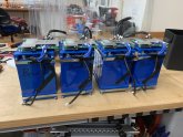
JoeHam, my initial thought was to forego the complication of external relays, contactors and the like and use a high power FET based BMS. I sourced some 120A FET based BMSs which, although they had all the required protective features and bluetooth connectivity, (as well as the likelihood of being repurposed for my house bank) lead me to an installation of four parallel 60Ah 12V LFP batteries for a 240Ah bank. I dutifully went through the process of constructing the bank, modifying the BMSs for real world 120A+ continuous current, testing for same, and came up with this configuration here:

IMG_0602.jpeg

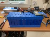
As I continued to work it, fiddling to fit in battery boxes, etc, I came to believe this was an ungainly and complicated approach. The more I struggled with its many large wires, the more I came to see the simplicity of having a single logical battery bank with a BMS capable of driving a big relay. I liked what I saw in the Chargery BMS, although it did not have a bluetooth option, so ordered one. While (still) waiting for this to arrive, I thought maybe I could even use the same 3P4S configuration I intended to use in my house bank for the bow thruster. After all, this is a 180Ah battery, close to the 200Ah AGMs already being used. To solve the issue of bluetooth connectivity, I installed one of my 120A BMSs in monitoring mode only, so I could keep an eye on what was happening internally. This battery shown here:

IMG_0651.jpeg

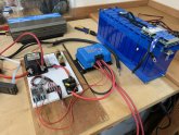
Here is my current test set-up. All pieces work as expected, just waiting for the Chargery BMS to arrive before smoke testing the system as a whole.

IMG_0689.jpeg

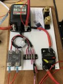
This is my control board. BlueSea 7713 latching relay to control the load. Opto Coupler to control the Victron B2B charger, circuit breaker for the charge side. As you can see, still waiting for a shunt, but considering installing this one.

IMG_0690.jpeg

Of course, with time on my hands now, I kept thinking... What about using a large house bank to drive both thrusters? This would be simpler, resulting in fewer LFPs overall, and even less weight. I already have 2/0 wire in place to the bow. I can run another 4/0 cable to help keep voltage up at the thruster under load and continue to keep the alternator on line when operating the thruster. So Plan C, as it were, is to temporarily remove the existing AGMs from the thruster, run additional 4/0 cables to the thruster from my current AGM bank, and see how it works.

Sadly, with my boat on the east coast, me on the west coast, and everything under varying degrees of lockdown, this may be delayed to mid-summer or beyond.

And so it goes...
 
So I would vote for your stated configuration 2.

Thats 4 12v nominal batteries that each need a 125 amp BMS.

Anyone have experience with a 12v 125 amp BMS?
Why would you want a 125A BMS? I would use dc-dc charger-controller (can also be mppt charger controller) of max 50A (Victron has a great one), for managed charging from the main AGM batteries (preferably from the cranking bank) and a simple BMS on the 3.2V cells or if you want to use a drop in LFP batteries, these already have their BMS.. For the LFP output you do not go through the BMS — am I missing something?
 
Nevertheless, a very nice and clean test bench! Doing some of the testing on the boat, currently docked in Palm Beach, while I live in Boston is a real pain.

This project is on hold at present awaiting a Chargery BMS to arrive for testing. (China is a black hole for shipping items just now.). Nevertheless, perhaps an update or two is in order. First, understand that my intention is indeed to replace all batteries aboard with LFPs, save the engine start battery. Call it a winter project. I chose Fortune 60Ah cells for their apparent robustness, geometry constraints in my house battery bank area, and my desire to have only one common cell in use aboard to simplify cell replacement if need be. My initial thought was to replace the bow thruster AGMs with LFPs and, if that worked, continue on. If that did not work well, return to AGMs in the bow and, to retain my original investment in LFPs, repurpose these cells for use when upgrading my house bank.

JoeHam, my initial thought was to forego the complication of external relays, contactors and the like and use a high power FET based BMS. I sourced some 120A FET based BMSs which, although they had all the required protective features and bluetooth connectivity, (as well as the likelihood of being repurposed for my house bank) lead me to an installation of four parallel 60Ah 12V LFP batteries for a 240Ah bank. I dutifully went through the process of constructing the bank, modifying the BMSs for real world 120A+ continuous current, testing for same, and came up with this configuration here:

View attachment 11312

As I continued to work it, fiddling to fit in battery boxes, etc, I came to believe this was an ungainly and complicated approach. The more I struggled with its many large wires, the more I came to see the simplicity of having a single logical battery bank with a BMS capable of driving a big relay. I liked what I saw in the Chargery BMS, although it did not have a bluetooth option, so ordered one. While (still) waiting for this to arrive, I thought maybe I could even use the same 3P4S configuration I intended to use in my house bank for the bow thruster. After all, this is a 180Ah battery, close to the 200Ah AGMs already being used. To solve the issue of bluetooth connectivity, I installed one of my 120A BMSs in monitoring mode only, so I could keep an eye on what was happening internally. This battery shown here:

View attachment 11314

Here is my current test set-up. All pieces work as expected, just waiting for the Chargery BMS to arrive before smoke testing the system as a whole.

View attachment 11317

This is my control board. BlueSea 7713 latching relay to control the load. Opto Coupler to control the Victron B2B charger, circuit breaker for the charge side. As you can see, still waiting for a shunt, but considering installing this one.

View attachment 11318

Of course, with time on my hands now, I kept thinking... What about using a large house bank to drive both thrusters? This would be simpler, resulting in fewer LFPs overall, and even less weight. I already have 2/0 wire in place to the bow. I can run another 4/0 cable to help keep voltage up at the thruster under load and continue to keep the alternator on line when operating the thruster. So Plan C, as it were, is to temporarily remove the existing AGMs from the thruster, run additional 4/0 cables to the thruster from my current AGM bank, and see how it works.

Sadly, with my boat on the east coast, me on the west coast, and everything under varying degrees of lockdown, this may be delayed to mid-summer or beyond.

And so it goes...
 
Very nice test setup and great first class components. I especially like the solid state relay.

The Chargery BMS was on my list also, but I ended up going with the Electrodaucus even before Will reviewed it. I would encourage you to give it a second or even a third look. Will has a great review on it on his YouTube channel, and also a not so flattering one on the Chargery.

I am using 10p4s 100Ah fortune cells for the main house bank (12 V @ 1000Ah) and a separate 2p4s 100Ah (12 V @ 200 Ah) set of cells for the start bank. The main reason for the Electrodaucus was that it does NOT shut off the cells which means no high power FETs to die. The normal mode of use for this BMS is to shut down the charge sources or discharge loads. The idea of giving something the built in ability to turn the battery off just seemed insane. It is fine to shut down your batteries if you have a solar shed, but not if you are in the middle of the pacific, at night, just outside of a narrow channel etc etc.

I am giving the Electrodaucus BMS the ability to turn off the solar charge controller, the MC612 Balmar alternator regulator, and the Samlex 30-12 inveter/charger. It is also going to be connected to a 110dB piezoelectric buzzer so if it shuts something down, I want to know about it. The Electrodaucus can be ordered with a WiFi module if that is important for remote monitoring.

Even though it probably won’t be needed as I bought all new identical same size cells, I also added a pair of 12V 4s 6 amp balance modules from the electric car parts company. One for the house battery, the other for the start battery. The balance function on the both the Electrodaucus and the Chargery is pretty pitiful, so if things do go bad then at least something is there to try to get it all back level again. It is probably a waste of money but it gave me a nice fuzzy feeling for it to be there.

I do not have a bow thruster, but everyone I know that has one, also has a separate battery for it. I have talked to a few dealers and all insist on the dedicated battery as their belief is that the voltage drop is just too high even using 4/0 cable. There are many voltage drop calculators online. I used one and plugged in your 360 amps, 12 Volts, and took a guess of 10 meters from house bank to the load and got a drop of 9.6 percent which is a bit high.

I have no pictures yet of what I have done, as it isn’t done yet. I am on the boat in Panama and getting things from the USA to here takes over three months due to officialdom.

John.
 
OK, I’m returning to this thread after a few months. I’ve enjoyed refreshing myself on conversations from earlier this year. Like you, @John Simmons , I’m still at distance from my boat which is now in winter storage in WI, which makes real-time modifications challenging. Despite covid restrictions, I managed to complete an eighteen day dash from the Connecticut River, up the Hudson, through the Erie Canal, and across Lakes, Erie, Huron and Michigan. I can say that new house batteries are on the priority list for this winter. Concurrently, I will have a custom alternator & smart regulator installed. As well, a Rev1 solution for the thruster issue could happen. All covid-permitting, of course. In no particular order then, here are my current thoughts, laid out here mostly as a summary. As usual, all comments welcome.

The alternator (no generator aboard):
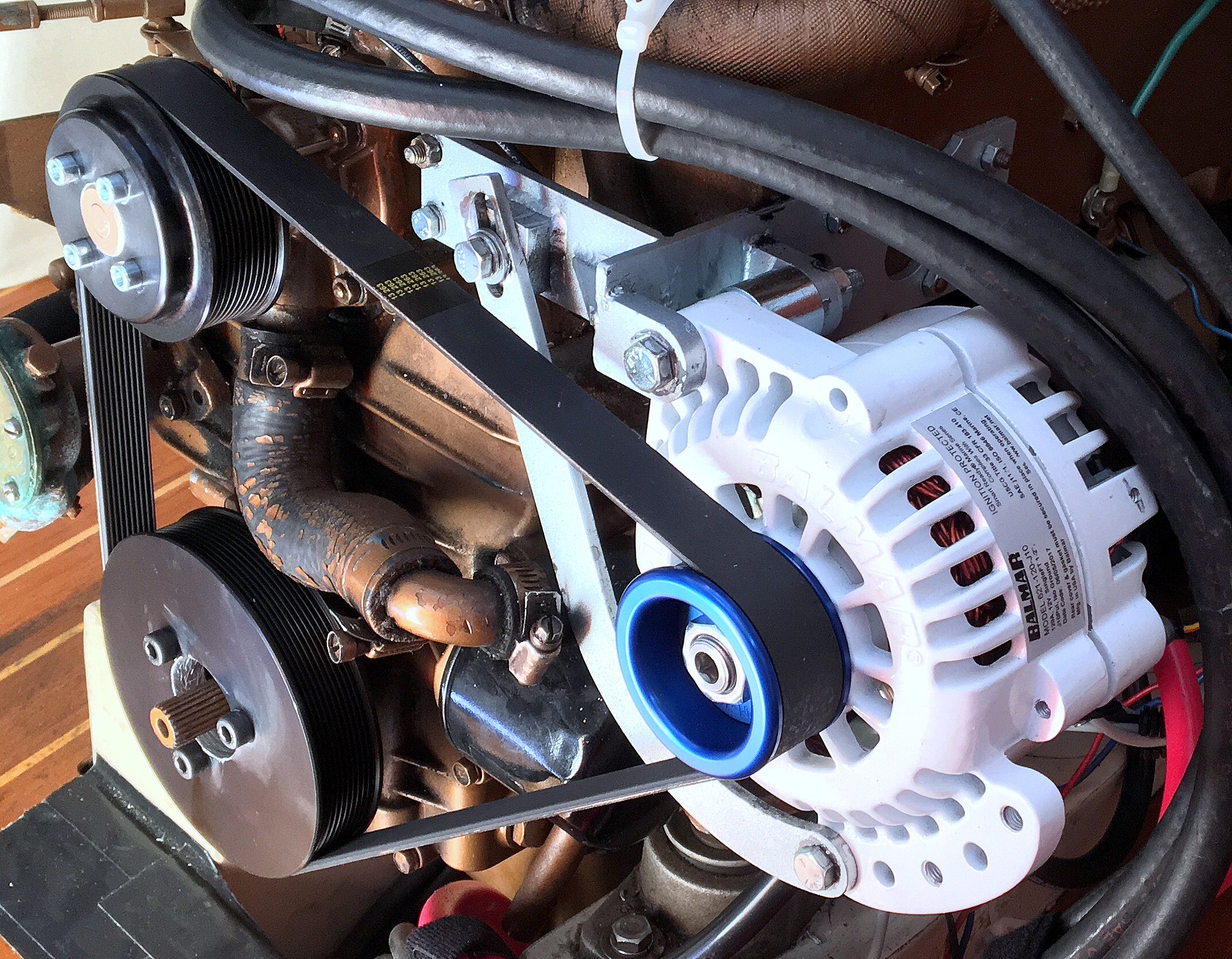
I’d like to have the ability to run AC while underway when it’s exceedingly hot and sticky outside. For me, this is two 16K Btu units drawing some 3KW at full bore. Current thinking is to install a 360A alternator with external diodes and (likely a Wakespeed) programmable regulator. Unlike other regulators I am aware of, this one can shift from absorption to float based on measured residual charge current (x/C) using the same shunt I already have installed.

House bank:
The more I thought about it, the less I liked the idea that my house LFPs could take themselves off-line either individually, (cascading perhaps), in the case of discreet batteries with internal BMS, or summarily if tended by a master BMS. I know the probability of an LV or HV disconnect is low if the components are of quality and the system is designed properly, but such an event would likely have high consequences if it were to occur. In particular, I’d like to be able to safely continue on my journey, while navigating with proper lights and equipment, until such time as I could address the root cause. So, I’m now considering a hybrid LFP-SLA house bank. This way, if the LFP portion goes off-line, there will at least be some SLA capacity available to keep the house lights on. I will have a series of warnings as an HV or LV disconnect begins to rear its ugly head, but I recognize I may not be able to react fast enough. A hybrid bank, with proper care in matching charge voltages across battery types, at least makes me feel better about this prospect. :)

With one 120Ah SLA for continuity in the current house bank space, I have room for a number of LFP options, with capacity depending mostly on form factor.
  • My original idea, Fortune 60A cells in 3P4S configuration for DIY 180AH battery, (100A cells are too tall), each with its own 120A FET based BMS w/Bluetooth. I can fit as many as eight of these batteries, for max 1440Ahr.
  • Commercially available drop-in LFPs with internal BMS. These range in price from as many as 8 Battleborn GC2s (no communication) for 1000Ah max, to as many as 10 Lithionics 125Ah G31s (w/Bluetooth) for 1250Ah max.
  • Commercially available external BMS, Victron SmartLithium 200Ah (w/Bluetooth) say, limited to 5 in parallel by their VE Bus BMS, for 1000Ah.
Note that each of the above solutions is capable of providing the 720A draw which might be required briefly if both thrusters were in operation at once. Though, of course, not with AC at the same time. :cool:

Thruster thoughts:
I’ve come to believe there are two primary issues with observed poor thruster operation, possibly three.
  • First is the voltage drop within an AGM battery under significant load which, particularly in older batteries, can result in a significantly lower voltage at the thruster motor as the load remains on line. Replacing the AGMs with LFPs should result in a more linear voltage curve under discharge, which ought to improve the voltage seen at the thruster motor under load.
  • Second is the difficulty of completely charging the AGM batteries underway with the oem alternator. The thrusters work well first thing in the morning, when their batteries have been charged by the Victron MultiPlus unit(s) overnight, but it the batteries fail to recover their full charge while underway so they can perform adequately when used again later that day. New alternator/regulator might help here. LFP acceptance rate higher as well.
  • Third is the possibility that the oem 2/0 gauge wires from the batteries to the thruster, though the distance be not far, may be undersized. I’ll do some voltage checks at the thruster motor under load and see what pops up.

@JohnSimmons: I note you are using a 10P4S configuration. This results in a large capacity 12V battery, capable of being monitored by a single BMS. Are you concerned about the inability to monitor individual cells within your 10P groupings? Or do you feel a 10P pack voltage difference is sufficient to alert you to possible cell imbalance?

Cheers,
Doug
 
I had a bit of hesitation at first with putting 10 of the Fortune cells in parallel knowing that if one went bad, it might be difficult to find. Then I thought, these things were supposed to be for underground mining and SHOULD have some attempt at quality control.

To be fair, we are not building a nuclear submarine here, we are making DIY batteries for a sailboat, so if one cell goes bad out of the 10 in parallel, I can take a couple of hours and isolate the cell without world ending consequences. I am a live-aboard boater, so I glance at the Electrodaucus display about 10 times a day. The 4 “cells” of 10 batteries each all stay nicely balanced within a couple of millivolts. If I ever see one drop like a rock, then I will start isolating and remove the problem cell.

I have been very happy with the Electrodaucus BMS. I especially like the idea that even if the BMS dies, the battery does not. It cannot take my cells offline, and it does a great job of monitoring the cells and shutting down the different changing sources (alternator, samlex Charger, MPPT controller). I just wish the display was larger and that the terminals on the back were for larger wires. Also the support that Dacian gave on his product was outstanding.

What engine do you have that you are planning on putting those large frame Alternators on? I looked on the Balmar site and for that size you need dual 1/2 inch V belts. I have known other sailors who tried going that route and were horribly aggravated at trying to match the two belts PERFECTLY. If one was just a bit larger than the other, the smaller takes most of the load, the larger one slips, and the process goes downhill from there. I once found an article on this, where the author mentioned which manufactures had better quality control, that you should buy belts from the same lot, from the same date code, and even if possible sequentially manufactured.

Here is the article.


I have a 3KW Samlex inverter at 12 volts. Samlex recommends running TWO 2/0 cables in parallel for both positive and negative. I can see why, using the IR thermometer the existing cables show a noticeable rise in temperature at 200 amps, and there is a 0.4 V voltage drop. The original inverter on the boat was less than 1 KW and was hooked up with 1/0 wire.

I have no experience about trying to run 32k BTU AC’s from an alternator. I believe it is theoretically possible, yet you will be pushing your electric system right to the edge. Things are going to get real hot, real fast. Especially the alternator. Put a temperature sensor on it and ensure it has a generous amount of space around it for adequate cooling.
My advice here is to email Balmar Tech support, they are awesome.

With that much AC load, and I presume a good sized DC load of refrigerator, freezer, lights, gps, radar, fish finder, etc, would it not make sense to put in a generator? That way you can run AC at night on the anchor or whenever you feel like it without such huge loads on your dc system.

That huge alternator is NOT cheap, and a large enough inverter to confidently take care of your loads is going to set you back more than a few dollars. You are also talking about over 10k dollars in batteries.

A 6KW northern lights generator will cost less and give you much better results and last longer. I just changed out my Northern lights with 6000 hours from 1992. I sold it for 3000 dollars and got a new one for 11,000.

In contrast the battery system which I installed was
40 Fortune cells @$120 each = 4800 for 1000Ah
3kw Samlex inverter @ 1400
BMS, shunt, cables, terminal ends, hydraulic crimper, relays, fuses, terminal strips, bus bars, etc 1000

Total of 7200 dollars.

Do I expect the DC system to live 28 years like the generator? No Way.

In retrospect, I should have reduced my battery bank to half of its size and saved some money and space. Don’t tell my wife this.
 
@John Simmons My engine is a Yanmar 8LV-370, which uses a serpentine belt. Moving the alternator diodes outside the case (and cooling them actively if needed) goes a long way to reducing the heat generated by the alternator when it's working hard, so 360A is not impossible in a smaller frame alternator. I'm personally loathe to install a generator, but I understand why so many people are happy with them. I believe it depends on what side ot the exhaust you're on. :) I use one at my home in California where PG&E has a habit of disconnecting power when conditions favor wildfires and, lately, this is near constant.

Cheers
 
I have a serpentine belt also on my volvo MD22A running a 90 amp alternator. It was the retrofit sold by Balmar and has been an absolute God send. I am glad you do not have to deal with the dual belt setup as I mentioned before, it really is difficult to get it right.

Are you considering dual alternators, one on each engine, or do you only have one engine? I would also love to know which alternator you are looking at as I have never seen something with external mounted diodes actively cooled. Please send a link, I am curious. It sounds like a great idea.

Also what inverter are you running to support the AC’s? One 16k BTU Ac will be a starting current of 18 Amps @ 120V, and a run current of 10 Amps. If one air con is running, and the other is starting you will see 28 amps AC @ 120V. This correlates roughly to about 280 Amps @ 12 V dropping to 200 Amps when both are running. Theoretically within the range of a good 3kW inverter, but barely. If you are lucky enough to have a 24Volt boat, then a 4kW should do the job no problem. If you are in the 12V world, have you given any thoughts for dual inverters? I would think that would be a great option as one 3KW inverter MIGHT do the job, but a dual setup would definitely get you what you need.

I just recently bought a Samlex 3012 and have been happy with it. The specs on it says it should work with your application, but I am not sure if it can be paralleled up or not. Donrowe.com had the lowest price. I chose it over the Victron due to where it had to fit, the Victron just did not have the correct form factor. I know that the Victron Phoenix series can be connected in parallel.

For your external separate cooled diodes, does the voltage regulator you are considering have provisions for dual temp sensing, one on the diodes, and the other on the case? I would think that with as much power as you are going to be pulling off of the unit, it is going to be hot, and protecting both components would be important.

This has been an enjoyable discussion, and I would love to see what you end up with.
 
Single engine here and, because of the uniquely mounted alternator, there are challenges getting anything of-the-shelf to fit. I've been unable to source a second alternator kit for this engine, despite the Yanmar reps saying it was in the works. The existing alternator is pad-mounted to the engine block with oddly spaced stand-offs. I'm guessing we'll have to build a bracket to mimic the offset mounts on one side yet allow for whatever mounting might be required for the replacement alternator on the other. I do not know which alternator will replace the original yet. I'm working with a guy named Mark Grasser, website here: https://markgrasser.com

I have two Victron MultiPlus 3000 inverters set up to operate in parallel for redundancy, each on its own 30A shore power feed. I suspect Victron would prefer to see them wired in series on a single 50A shore power feed, one acting as master and one as slave. However, I prefer the redundancy afforded by parallel units, as well as not having to always drag around a 50A shore power cord if I only need one 30A or less. I find a single 30A cord is all I need in most places north of the Mason Dixon Line. At present, both AC units run on the same 110V leg, and either MultiPlus can handle the AC starting surge and running loads while the other supplies additional 110V or 12V charging as needed. Both AC units now have soft starts attached, which enables either MultiPlus to start and run both units. This was not the case when I took delivery, when the Multis (inverting) could not start the second AC unit when the first was already running... :) If I were to do this again, I would spec two Quattro 4500 units instead, just for the additional headroom.

The Wakespeed has two external temp sensors, one for the battery bank and one for the alternator, each independently programmable, as well as one internal sensor that monitors the regulator itself. I presume that the battery bank temp sensor could be repurposed to monitor the diodes given that I'm installing LFPs. However, it might take some trial and error to decide just how much to ramp down the charge current if the diodes are truly getting too hot... Mark says he hasn't had issues with diodes overheating and his box now has two active fans attached for cooling I believe.

I'm curious to see what I end up with as well. Lots of good ideas (and questions) out there!

Doug
 
Okay, I just read the entire thread from the top again to refresh my memory.

I would seriously take a look at the Electrodaucus SBMS0 rather than the Chargery. It is in my opinion a much more elegant solution and there is no chance of your batteries dropping offline. The Chargery just seemed like it was aimed at an ebike or something similar, it felt like I should plug a skateboard into it or something.

If you haven’t installed anything yet and you are still exploring alternatives, it is a good opportunity to see a different approach. The Electrodaucus shuts down your charging sources if the voltage gets too high, and it shuts down the loads if the voltage is too low. I believe it is the best solution out there right now (it would be perfect if the display was larger, and the wire connections were more robust, oh and mounting it is a bit of a pain In the ass as there isn’t much of a lip)

I used it to control the Samlex, the Morningstar MPPT, and the Balmar regulator. The Samlex and the MPPT required a +12V signal to shut down, while the regulator needed a 0. There is only one charge disable output from the Electrodaucus so I fed that into this


I then used either the NO or the NC of the relays such that when the Electrodaucus was saying everything was okay, then Charging was enabled. As soon as the Electrodaucus said voltage too high, and shut the relays off, the relays were configured to send 12V to Samlex, 12V to MPPT, and 0V to Balmar. Works awesome, no high power electronics, no way of losing the battery bank, and if it ever craps out, it is easy to repair or work around.

John
 
@John Simmons I like what I've seen so far in the electrodacus bms. I'm quite certain I could get it to turn off my MultiPlus(es), MPPT Solar, and perhaps disconnect my alternator field if I wanted. I would seriously consider something like this for 'normal' house loads, even the 300A or so my AC units require. However, I would really like to ditch my dedicated thruster batteries in favor of using the house bank to drive them. For this to work, using a single bms with a large xP4S Fortune cell house bank to supply 8600W, will require inter-cell connectors capable of at least 700A. That means custom connectors for the entire bank, or using 5 of the supplied connectors per terminal, 10 (or wire) where the parallel cells need to interconnect for series. 5 of the supplied bars won't fit with the existing nylock nuts, so 10 is out of the question. Splitting the bank into two or even three smaller logical batteries and using a bms for each only complicates the assorted control circuitry beyond my comfort level... This is primarily why I'm leaning toward a discreet set of parallel batteries, each with their own (probably FET based) bms, and placing enough of them in parallel to comfortably handle the loads I expect they will see. Your comments?
 
Just some quick math to see if replacing a thruster battery makes sense.

given 700 amps @12 V.

Going online, and plugging into google “resistance of 2/0 copper wire“ just for giggles
We get

AWGDiameterCopper resistance
inchMilli ohms per meter
0000 (4/0)0.46000.1608
000 (3/0)0.40960.2028
00 (2/0)0.36480.2557

now going online again to https://www.calculator.net/voltage-drop-calculator.html

Plugging in some “guessy” numbers

4/0 cable, 13.3v 700 amps, 10m gives 10m was a butt pull number.

Voltage drop: 2.25
Voltage drop percentage: 16.68%
Voltage at the end: 11.25

Not good.


Plugging in some More “guessy” numbers

4 conductors of 2/0 cable in parallel on both hot and ground, 700 amps, 10m gives

Voltage drop: 0.89
Voltage drop percentage: 6.63%
Voltage at the end: 12.61

Not bad. Possible, let’s look at costs.


4 pieces red 2/0 wire in parallel =(4 * 3.3 ft/meter * 10 meters) = 132 feet
4 pieces black 2/0 wire in parallel =(4 * 3.3 ft/meter * 10 meters) = 132 feet

going to https://www.bestboatwire.com/

we get a cost of 132 feet red @ $5.29 per foot = 698 dollars
we get a cost of 132 feet black @ $5.29 per foot = 698 dollars

About 1400 dollars in wire. Ouch!

2/0 cable weighs in at 402 pound per 1000 feet, so total weight of wire would be:
264 feet * 402 pound per 1000 feet = 106 pounds of wire. (About what a good battery weighs)

The 10m one way distance I chose was just a guess, only you know your boat. Plug in the real numbers and see if it makes any sense at all.

My guess is that you are going to be stuck with separate thruster batteries.

As for the terminals of the fortune batteries, they are a grid. This is Key to understanding current sharing.
One 4s1p battery alone won’t cut it. Each plate is only good for 100 amps.
So if you had 7 of them at 4s1p that means each one can source 100 amps, and it is fine. 7 individual batteries.

Note that when assembling them in a series parallel grid, the parallel must be an EVEN number so 4s7p doesn’t work well, you have a “gap”. Look at the video Will put out on how to lay out the Fortune Bus Bars. You need 4s8p otherwise the grid gets messed up. But let’s ignore that and go with 7.

In order to safely get 700 amps out of this you would need 7 positive leads at the top of the battery going to a bus bar, where the 4 2/0 wires are hooked up, and the same for the negative side. 7 negative leads going out the bottom of the battery .That way any fortune bus bar will only carry 100 amps, and all is well.

Sorry to go into lecture mode.

John
 
John, no worries about 'lecture mode'. We may be talking across one another, at least on battery topology. Yes, seven 4S1P batteries in parallel, each with their own leads to the pos and neg busses would work a treat and provide the required power within single Fortune bus bar specs. In my case, I plan to use a 3P4S configuration of 60Ah cells for a 12V 180Ah battery. 8 of these in parallel will easily handle the above loads as well as fit in my available space, and provide a large overall house bank rating. In this case, however, each battery needs its own 4S bms, which complicates the install a bit. Not terribly, though, if they are FET based. And bluetooth monitoring is a bonus.

Like you, I've done the math on V drop across the wires to the bow thruster. From the house bank the wire length is about 12 ft. Even two parallel lengths of 4/0 would be acceptable to me in this instance for the simplicity of ditching batteries in the bow. If it works to use the house bank, I will. If not, I'll drop in a 180Ah or 240Ah LFP where the AGMs are now and be done with it, using the gear outlined above. Electrodacus or Chargery bms would work fine here. As a bonus, I have spare FET based BMSs around with bluetooth capability which I can position atop each battery simply to monitor the cells. Et voila!

And yes, I know that removing these loads from the house bank would permit me to construct a large house bank in xP4S format, where a single Electrodacus BMS could monitor it, much as you have done. However, I live aboard only when cruising for a few weeks at a time, and my dates are constricted. Having to bring down my electrical system to find and replace a cell or two, despite the long odds this might ever have to be done, isn't something that would work for me at this point.

LMK if you come across a BMS which can monitor the cells of 8 individual 3P4S batteries, which has the ability to simultaneously control 2 Victron MultiPlus 3000s, an MPPT, alternator field disconnect, bluetooth monitoring... :)

But I digress. We started out talking about thruster batteries. :cool:

Doug
 
Back
Top