diy solar

diy solar

Lithium Charging w/alternator

I understand the programming of the external regulator. I have been running my engine and alternator without a temperature sensor for 6 years with no issue. So, my concern is protecting the alternator from the BMS shutting down.
 
I understand the programming of the external regulator. I have been running my engine and alternator without a temperature sensor for 6 years with no issue. So, my concern is protecting the alternator from the BMS shutting down.
Is this a demonstrated problem?
 
You have been running your alternator with lead acid/AGM batteries for six years. Lithium is different. It will take all the alternator can give for as long as it needs. It has a totally different charge profile than lead and can take a charge faster. This can place a much larger power demand on the alternator and MAY cause it to overheat and burn up.

Placing a lead acid in parallel with the lithiums will keep your diodes and electrical system from a catastrophic voltage rise if the BMS disconnects. Will it save your alternator from overheating? No, it will not. The ONLY thing that will save that expensive Balmar Alternator is a temp sensor. It is your boat, you can do whatever you want.

I strongly advise you to post these questions to Balmar. They are great people, and their technical support is based on engineering and design, not on guess work and chance. They have never steered me wrong. Their products are expensive, but in my opinion worth it.
 
The lithiums take a 40 Amp charge each for a total of 80 Amps. If I put a resistor on the alternator, it can reduce output. But, I will contact Balmar and check with them as well. I did locate a temp sensor, but I have been told it is not necessary by local marine electrician, will double check with Balmar.
 
@sailing gal
The temp sensor is $30 for balmar regulator.

you might be best off leaving your current setup (add temp probe) and a battery to battery charger that is 80a or so.
 
After speaking with Balmar, I decided to upgrade my alternator regulator to the MC 614 series which has LiFePO4 programmable settings built in, plus the temperature sensor. I suspect that the AGM starter battery will be just fine since the LFP batteries' BMS uses tolerances acceptable to the AGM.
 
Great plan. Balmar knows their stuff. Since you say that you are limited to 40 amps charging current on each of your two Lithium ion batteries, for a total of 80 Amps, you should look at the Amp Manger feature. It is located in the Advanced Program features and is a setting that will limit the maximum field current and therefore limit the maximum output current of the alternator. Adjustable in 2% increments.

Balmar tech support rocks. I wish all manufacturers of marine stuff was that good.
 
I have a balmar mc612 alternator connected to a 12V 1000Ah LiFePho4 bank. I contacted Balmar about what settings should be programmed in, and they were super helpful.

One of the items that they were insistent about installing was a alternator protection device.


According to Balmar it will save your alternator and any electronics connected to the alternator in case the battery becomes disconnected either through some idiot switching the battery switch to OFF or the BMS taking the main battery offline. When the load is suddenly disconnected from an alternator, the output voltage spikes dramatically and at a minimum the diodes in the alternator are destroyed. The open circuit protection device that Balmar told me to buy keeps a load on the alternator at all times and supposedly keeps this from happening. I have never gone wrong listening to the Balmar tech support. I don’t have the courage to actually test the thing to see if it works though.

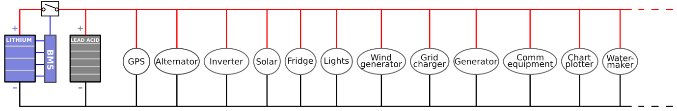
I presently have a similar hybrid system. Batt 1 is the house LiFePho4 1000 Ah. Batt 2 is a Lead Acid Starting Battery.

All of my charging sources (Balmar Alternator with MC612, Samlex inverter Charger, and Morning Star MPPT controller are programmed for Lithium charge profile). The BMS I use is the Electrodaucus SBMS0.

The sole exception is ONE 20 Amp Lead Acid Battery 120V charger that is connected to the starting battery for when I am on shore power or when the generator is on.

My usage profile is switch the 1/2/Both/Off battery switch to 2 (Start battery) start the engine or generator and let the alternator charge the starting battery for a few minutes as I pick up the anchor etc. Then I switch over to Battery 1 which is the House LiFePho4 and I just leave it like that.

My use model for the boat while at anchor or while sailing is one to two hours per day of generator run time to make water, cool down,the holding plate, and fast charge the Lithium Bank. At that time the small battery charger is also topping up the start battery. During the day the solar panels are charging the lithium bank.

Note that both banks are separated by the battery switch, but I can combine them if I want as was mentioned in the previous article. I have done that as the voltages are similar enough as to not cause any major problems, but in general the charge voltages of lithium batteries are higher than Lead Acid. If you permanently parallel connect your lead acid with the Lithium, you will overcharge the lead batteries and shorten their life.

My eventual goal is to move to all Lithium and get rid of the lead acid side completely. Unfortunately for me, the starting battery is only 6 months old, so I will continue using this hybrid system.

One of the other boats on the dock has a similar setup and he uses a battery to battery charger to top up his lead acid cells. I am only using the 120V AC charger I have because I already own it, and my stated goal is to move totally to Lithium when the last lead acid dies.

If I was going to keep a lead acid battery permanently, I would go with the Battery to Battery charger.

John.
Thanks. Great explanation. I’m afraid of paralleling my 200a FLA and 150A LiFePO4 over a 6awg wire I’m using to switch my solar charger to charge the FLA and LiFePO4. What rule could be used the safely parallel the banks? My LFP bank is normally at 13.4 90% SOC for me and FLA maybe 12.5v 95% Soc. I Think the FLA should only take 10a at 95% SOC?
 
FYI you can grab that APD from battleborn w/free shipping for $74 I think
 
Check out this hybrid system.

This is the second of such articles on this forum and I found them both very useful.
I now have a hybrid system and it works exactly as advertised, in that my alternator is protected from the BMS disconnecting the battery and the LI gets charged quickly.

So with this hybrid system I would switch my solar charge controller back to a lead acid charging profile rather than LifePo4 one it is set at now?
 
My 400 Ah of LFPs are installed and everything has been wired up, (still waiting on the delivery of the Balmar MC614). I have reprogrammed my Xantrex LinkPro with the parameters from the Spec sheet that applies to my batteries. But it is not behaving properly. For example, when the batteries are fully charged, it does not say "full" like it should. The other day the hours available showed 120 instead of 240, even though they were thoroughly charged. After I turned on the battery charger at the dock, they went back to 240 h very quickly. It is basically working, showing me the full batteries, but it seems a little buggy. Anybody have this experience?
 

I'm not doubting that the phenomonon that they are describing exists, and that their products effectively manage the situation, but their test seems to be biased in that they used a relatively small pulley on the motor, and a relatively large pulley in the alternator resulting in alternator speeds much lower that typical in a automotive application, which exagerates the effect they are demonstrating.

By comparision the crankshaft pully on my Jeep is over 7" in diameter and my alternator pulley is less than 2" in diameter. Even at a 750 RPM idle, my alternatoris turning at over 2600 RPM, and at typical cruising speed the alternator is about 7500 RPM, almost twice the speed of their "highest" speed.

I do completely agree with their conclusions that typical automotive alternators are phenominally inefficient and that the charging Lithium batteries with an alternator is problematic without some way to control the current.

It would be really cool if you could have an ammeter monitoring the charging current and a current adjustment knob, so that you could set the charge current for your drive based on the amount of charge needed and the length of your drive to minimize the impact on fuel economy and only work the alternator as hard as needed to get the charge you needed during the drive.
 
I mean, it kind of does that right? Alternator turns full amps to charge batteries, then it goes down to no output. Same amount of fuel/power provided the efficiency is the same at all RPM (im sure it isnt, but probably a negligible amount difference realistically).

Essentially, because there is no resistance in the LFP battery, the voltage regulator provides full field power at all RPM. This creates lots of heat which burns it out, because its pulling full power with lower fan speed...

The temp sender is $30...
 
I think the problem is that many people in boats and RVs will idle the engine to charge the batteries and if you set the alternator up to spin fast enough to cool at idle you may over rev it when cruising depending on the rev range of your engine.
 
So, my Xantrex LinkPro is not designed to monitor LiFePO4 batteries, per Xantrex. I do have a Blue Sky MPPT controller that gives me pretty good info, and I have a phone app that connects to the BMS's of my batteries. But, I like to have something on my panel. So, any recommendations on something would be a good substitute for my LinkPro?
 
The lithiums take a 40 Amp charge each for a total of 80 Amps. If I put a resistor on the alternator, it can reduce output. But, I will contact Balmar and check with them as well. I did locate a temp sensor, but I have been told it is not necessary by local marine electrician, will double check with Balmar.
You're misunderstanding this point.

1) The LFP battery BMS can only handle 40A or approx 80A for two in parallel.

2) Parallel FET based BMS's is a dangerous path to count on as one high resistance connection, and one battery is taking more current than the other and over loading the BMS.

3) The cells will take what ever you can throw at them but the BMS may not handle that and disconnect. The alternator can still over heat and burn up supplying 80A continuously. No small frame alternator, not even a Balmar, is rated for constant duty and the output rating is a cold rating. Your external regulator should be set up to deliver no more than about 50-60A max to the batteries and it should still utilize an alternator temp sensor.

I've seen many, many, many marine alternators cooked by LiFePO4 batteries and an incorrectly programmed regulator.
I did end up replacing the regulator with an MC 614 and added an alternator temp sensor. I do think I have the bases covered now.
 
Those balmar temp sensors like to fail so its a good idea to keep a spare one around.
 
That battery linked by the OP is L-ion. Not a great idea on a boat. Lifepo4 is a better option. That supplier also has those banks but are currently sold out I believe
 
Back
Top