diy solar

diy solar

LittoKala 100AH Cells

The Overkill Solar BMS is awesome. Will just released a review vid for it. If you haven't seen it, go look. He mentioned how great the BT was. I am charging in my shop, which is on the other side of the green wall where my finger is pointing. I have a solid connection from my la-z-boy through the wall, through my truck, and through the window :cool:

InkedIMG_8732_LI.jpg
 
I've been slow with building my pack using these cells but am just completing top balancing with the iCharger X6. From the 3.000V per cell they were received at, exactly 100ah was required to hit 3.6vpc / 14.4v. I'll begin discharge testing tonight (not very scientific, chinese smart bms + victron BMV712) but that should give me a ballpark. Even if it's not the exact number I'd see testing with one of those resistive fan things, it is the number I'll see every day relying on the BMV or BMS for SOC.

I was incorrect once I lined my cells up, one of them was slightly bloated at 3.000V when I received it. It doesn't seem any worse sitting at 3.6v. I don't even intend to clamp these cells, just tape, so we'll see what kind of life I get out of them riding on the tongue of a camper trailer.
 
They ARRIVED this morning...finally!!! Ordered 15 Jan 2021, and arrived 14 Mar 2021...within the estimated delivery timeframe by LiitiKala/AliExpress. Cosmetically they are fine. Put a straight edge on all the sides...not as flat though as I thought they'd be, but certainly acceptable. Initial voltage of the four cells...3.020, 3.002, 2.999, 2.998 or 22mv delta.

Terminals were all in good shape with no marks. The four busbars were rather thin, and the threads on the screws were about 7/16'. The depth of the threads on the cells were about 1/4". So all, be careful when tightening down the busbars with other added thickness not to bust through base of threads!!!!! When I ran a screw into each of the cells threads, I did notice a little intermittent resistance, meaning that the threads weren't that clean. But after CAREFULLY running a screw in and out of threads a few times, the threads were fine. So all...be careful when initially putting screws in threads.

The cells are in parallel now and doing a top balance with a bench charger to 3.6V. No BMS yet...and watching VERY closely.

I chose to go the route of a 120A BMS w/BT module from AliX...$70 delivered to my door scheduled for 16 Apr (link below). I will let let all know how this BMS performs next month. Again...hurrying up to wait! :rolleyes:

My previous cell build was the EVE 280Ah cells. When I opened the box this morning for these 100Ah cell, I was VERY surprised how small these cells are. And, that is a good thing! As my intention for these 100Ah cells is to build the small portable power/solar pack (post #65) for ham radio field operations, and a quick "go to" pack for camping.

Keep charged my friends!!!
Mike

 
Last edited:
Here is the link of the guy that already did this project...pretty slick. He used 80ah cells, but plenty of room for the 100ah cells and the meters, recepticles, switch, etc.


Mike
I always watch these kinds of videos to see how people mount the cells, and seldom do I ever see it addressed. Did I miss it in this video, too?

This is constantly a conundrum in my builds. Making sure the cells are joined together and act as a single brick, and then making sure that brick doesn't fly around in whatever imperfect box I've settled on. Drop in style batteries have it a little easier because they 1) can use boxes built to their spec and 2) just wire terminals on top instead of panel mount sockets on the sides.

Part of me just wants to gorilla tape the cells together, use that white glue seen in so many drop-in batteries to anchor it to the bottom of the battery box (ammo can, whatever) and then foam insulation board on the side. Sounds kind of iffy relying on the glue to prevent vertical movement though, and the only other option to prevent it from lifting up and down would be to mount cells on their sides and add foam to the ammo can lid.

This is kind of a unique challenge for these smaller cells destine for mobile applications. Clamp and restrain without making your battery box twice the size of the cells themselves.
I share your conundrum. The reference video does show a fabricated restraining bracket at the 9:20 mark. However this only restricted movement of "two of the three planes" (left/right, front/back). However that bracket does nothing for third plane (up/down). Tip/turn the container over, and there is a big problem. I will be doing some finagling to keep the cells still on all three planes...additional brackets, glue, padding, we shall see.

I will be adding a thin layer of protection between the cells as well, before affixing cells together. I will be using the 3M VHB tape between cells, and tape (type TBD...Gorilla, Kapton) to wrap around all four cells. Highly critical is to ensure the tops of the cells are fully insulating from shorting while in the ammo box. I will be using Kapton tape and additional insulating padding for tops of cells.

BTW...I have 6mm x 25mm studs and flanges nuts on order, and will be fabricating better busbars, to replace the provided chintzy screws and busbars.

Have fun!!!
Yikes, I went with the 25mm originally and within a minute of receiving them and testing, had ordered 16mm. Those work much better, I didn't realize how shallow the terminals were. 16mm doesn't look out of place and can accommodate bus bars twice as thick as the ones we receive with the cells + two connections on main positive and negative. And still have thread to spare. 25mm leaves a lot.

Thanks for the timestamp. I'd tape my cells with VHB too, but the bulging of one of my cells makes that feel like a bad idea, the gap would require doubling up tape (possibly more) and I wouldn't want to apply tape to the bulged area as that could stretch the bus bar distance too far.

Jealous you have yours in parallel, I tried to request more bus bars from the seller but they didn't understand what I was saying. While my RC balance charger had no trouble completing a slow balance on the pack without much throttling (i.e. didn't drop to 2 amps charge for 4 hours trying to juggle the high cell) they did come to rest at a 40mv difference after hitting 3.6v together. Once I get the BMS set up I'll do my discharge and charge back up to 13.8 - which will be the highest I go. Willing to bet I won't have that significant of a difference staying between the shoulders, but I'll always have wondered if paralleling them would have made them perfect.
No need for 6 busbars to put in parallel. Use the four they gave you, then use 2 jumpers with alligator clips, ring/U terminals, or simply put the stripped end of the jumpers under the screws/washers. I am charging less than 10 amps. Just make sure the screws are fairly tight and you have at least 16AWG wire for jumpers (or there abouts), and you will be fine at low amp charging. Just make sure to charge at no more than 3.6v to be safe when in parallel. See pic, and please excuse the clutter.
 

Attachments

  • 20210314_143011-1_resized.jpg
    20210314_143011-1_resized.jpg
    59.1 KB · Views: 31
Last edited:
No need for 6 busbars to put in parallel. Use the four they gave you, then use 2 jumpers with alligator clips, ring/U terminals, or simply put the stripped end of the jumpers under the screws/washers. I am charging less than 10 amps. Just make sure the screws are fairly tight and you have at least 16AWG wire for jumpers (or there abouts), and you will be fine at low amp charging. Just make sure to charge at no more than 3.6v to be safe when in parallel. See pic, and please excuse the clutter.
Cool, I can do that. Thanks for the pic. Discharging now @ 13 amps and a pretty consistent 30mv difference, settles to 2mv instantly if I shut off the load. The low cell is the bloated one :| I noticed this ~30mv difference when first charging the pack (same cell) and replaced the balance harness which was pretty flimsy, shame that wasn't the culprit.

edit: first test complete, with a cell under voltage setting of 2.6v and a load of 13 amps on a 100ah 12v pack, I achieved 98.82ah. I'll charge back up in series and then do the parallel connection and charge to 3.6v, then repeat.

But almost 99ah is perfectly fine for me. After I top balance @ 3.6vpc I'll discharge again, then charge back up to my target voltage of 13.8/3.45vpc and discharge to wherever I want my bottom at. If I can float around in 80ah usable land it'll certainly satisfy my need, and hopefully be the last battery I install on this little pop up camper.
 
Last edited:
Under voltage setting of 2.6v,

I think the inverter will hit under voltage before that.

I ordered mine on Jan 14th, 2021, no updates on Fedex.
Alix says they have till April 24th to get here, what the LFE!
 
Under voltage setting of 2.6v,

I think the inverter will hit under voltage before that.

I ordered mine on Jan 14th, 2021, no updates on Fedex.
Alix says they have till April 24th to get here, what the LFE!
yup...only choice is to be patient. They will get there. BTW, where are you?
 
Under voltage setting of 2.6v,

I think the inverter will hit under voltage before that.

I ordered mine on Jan 14th, 2021, no updates on Fedex.
Alix says they have till April 24th to get here, what the LFE!

I think you're right, I did my discharging with a victron 12|250 inverter and I forget what I set the low voltage shutoff to. I did not have a low voltage alarm on the smart BMS, but I had let my phone's screen lock and figured maybe it reconnected and had cleared ?‍♂️

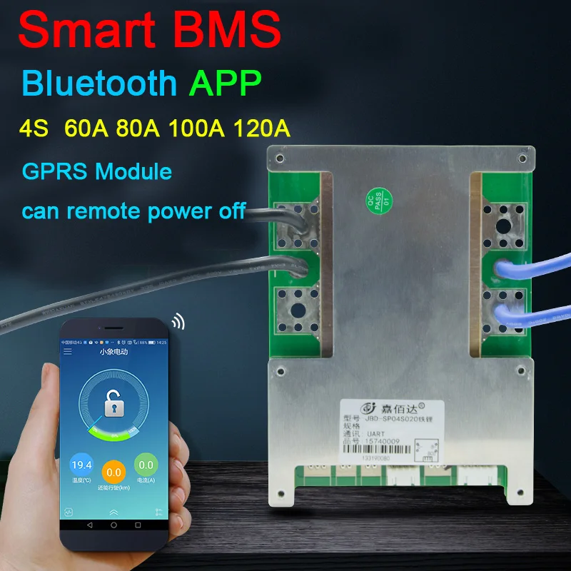
I didn't know the smart BMS units (overkill solar type) would adjust battery capacity without hitting the programmed low voltage disconnect, but it did (the 98.82ah figure)

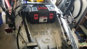
I charged it back up with a Victron MPPT and 24v power supply as PV, to see how wonky things would get in normal charging conditions without the aid of a RC hobby balance charger. The MPPT with aid of a Victron Smart BatterySense nailed 13.8v on the nose as measured by BMS and Victron app. This is better behavior than I get in my other setup with a BMV712 providing voltage and temp.

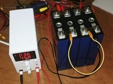
At a 20 amp charge rate I was obviously exceeding the balance ability of the BMS by an enormous factor, but at the end I was at 13.8v and a high cell of 3.472v, ~30mV delta. Once a brief absorption ended (to give additional balance time, but ended up not having any benefit), the cells instantly settled to 1mV difference. I could run this as is but I decided to parallel the cells and take them to 3.6v. I just completed this using the iCharger X6 once again at 30 amps, worked great and didn't overshoot.

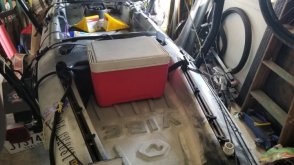
I'll let them hang out in parallel for a couple hours and then reassemble in series for another discharge test, then another charge through the MPPT to see if that 30mV high/low cell difference is gone at the same charge rate. I don't know if that's to be expected, this is my first time doing a proper top balance.

Just watched Will's video on the overkill solar bms and damn do I have cell envy. Would almost be worth getting in to 3d printing to try and make the cell caps that the Fortune cells have. Minimal bulk added, compression and mounting options all in one, terminal protection, a shelf for BMS or breaker. Would be so damn nice.
 
I suppose I may have had better luck ordering 8 and picking out the four best ones.

Seems like cell 3 (slightly bloated upon receiving) is still behaving weird. I can rule out the balance harness (replaced) and device (visible on both hobby charger and smart bms.) I can also rule out the bus bars as I'm sure I've mixed those up a dozen times and flipped them over. Cells 1 and 2 are perfect, always within 3mV from each other @ 0.2c. Cell 4 is within 8mV of those. And dreaded cell 3 is 40mV and seems a little jumpier.

Funny that for the last 4 builds now my crummiest cell has ended up as cell 3 by complete coincidence. One of those builds used 90ah decade-old K2 cells, of which one (cell 3) is crappy and limits the pack to 70ah. I ordered these to replace those :LOL:
A few comments. Have you tried shuffling the order of the cells? Second, seems that 40mv would not curtail 30Ah off the capacity :unsure: . Does the 70Ah capacity include the above 90% and below 10% "buffers"? What are you using as your upper and lower voltage disconnect parameter?
 
A few comments. Have you tried shuffling the order of the cells? Second, seems that 40mv would not curtail 30Ah off the capacity :unsure: . Does the 70Ah capacity include the above 90% and below 10% "buffers"? What are you using as your upper and lower voltage disconnect parameter?
Sorry, that 70ah figure is for the pack this build is destine to replace. I have not tried shuffling the cells but those past builds were all using different equipment, so it's just a fluke.

I ran another discharge test but didn't take it to low voltage cutoff. This was following the top balance. I pulled 93ah out @ 13a before cell 3 started to get in to the high 2.8's and the delta had grown to 90mV. I'm recharging now @ 25 amps with a 55mV difference, cell 3 being max as one would expect having the smallest capacity. Perhaps related to the bloated state the cell was received in.
I'd try shuffling the cells for the hell of it, and see if what was cell 3 is still temperamental. I'd swap inside cells with outside cells...or if original configuration was 1-2-3-4, I'd reorder to 3-1-4-2. Xuba recommended this when my 280Ah cells were exhibiting similar mv delta. See what happens. Be interesting.
 
The next chapter. In parallel, all cells topped off at 3.65V. Cells arrived at 3.020, 3.002, 2.999, 2.998. It took several days to fully charge with that small bench charger I have. Since I am waiting on the BMS delivery, I didn't want to leave them at top charge, and took them down to 3.3v. When the BMS gets here, I will do capacity test.
 
Sunday, March 21, 2021
1:57 PMMARCELINE, MOIn transit
1:51 AMCANADIAN, TXIn transit
Saturday, March 20, 2021
12:44 PMBELEN, NMIn transit
Friday, March 19, 2021
10:43 PMWILLIAMS, AZIn transit
10:33 AMSAN BERNARDINO, CAIn transit
Thursday, March 18, 2021
10:31 PMCARSON, CALeft FedEx origin facility
1:28 PMCARSON, CAArrived at FedEx location
12:00 AMCARSON, CAPicked up
Tuesday, January 26, 2021
11:25 PMShipment information sent to FedEx
 
Got em,

Cells were at:L
2.97, 2.99, 2.99 & 2.99

The BLACK ringed post is POSITIVE?
hmm, not sure what standard that is for DC cells.
 
Got em,

Cells were at:L
2.97, 2.99, 2.99 & 2.99

The BLACK ringed post is POSITIVE?
hmm, not sure what standard that is for DC cells.
I drew a red marker + on the top and sides of each cell. I just knew I wouldn't be thinking and look at that black ring and think it was negative and fry something
 
What enclosures will fit 4 of these?

Small ammo can?
Thats a good question. I haven't found anything that I am real happy with. I have a 16" tool box from walmart. The batt fits laying on its side about perfectly, with the Overkill BMS. But the tool box is much longer than necessary.

The other thing I tried is a little Igloo cooler. Not a bad fit, but a little larger all around. I don't have any pics with the batt installed, but these are the items

I would love to see something better
 

Attachments

  • 20210309_154320.jpg
    20210309_154320.jpg
    70.1 KB · Views: 11
  • 20210309_154405.jpg
    20210309_154405.jpg
    67.3 KB · Views: 11
Thats a good question. I haven't found anything that I am real happy with. I have a 16" tool box from walmart. The batt fits laying on its side about perfectly, with the Overkill BMS. But the tool box is much longer than necessary.

The other thing I tried is a little Igloo cooler. Not a bad fit, but a little larger all around. I don't have any pics with the batt installed, but these are the items

I would love to see something better
Yak guy, nice, waterproof or at least splash proof will be nice, I will dig in my garage tomorrow at lunch and see what I can find.
 

diy solar

diy solar
Back
Top