Joshua787
New Member
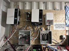
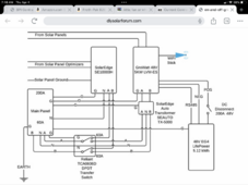
Would you mind double checking my wiring please? im new to this. solar systems are relatively new to Puerto Rico and the 3 electricians I know are not able to see the problem due to their low knowledge on solar.I don't need any pictures to know what the problem is.
But that's because I am familiar with their equipment.
And 40 years in the trade , doesn't hurt.