diy solar

diy solar

Looking for opinions on my solar diagram!

Abell

New Member
Joined
Mar 17, 2020
Messages
54
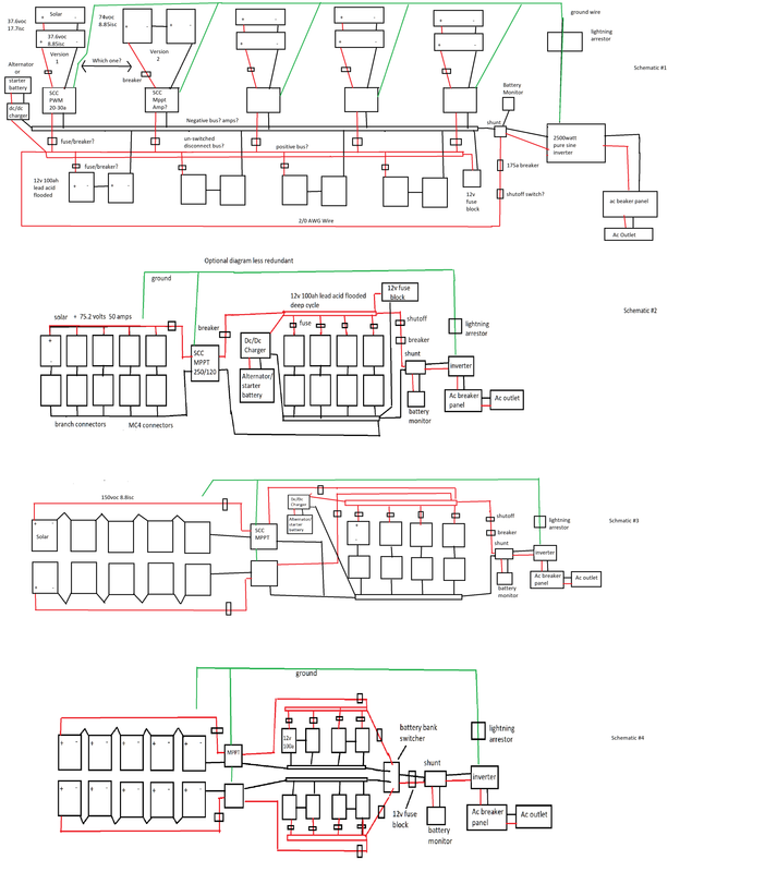
Hello, my names Abel. I'm new to solar. I been watching countless videos and i feel like my diagram is almost complete. Except ill need fuses for each battery. My biggest problem is i have 10 solar panels and if i do 5 in a string i'll need a monster controller to handle all those volts. Even with 4 panels is bad. So i'm thinking of doing a 48v battery system. Would anyone please take a look at the diagram i drew in paint to see if there are any errors or things you could improve? My diagram is only 8 panels of the 10 i have because if i do strings of 3 that gives me 9. If i do 2 panels in each string ill need 5 charge controllers? My panels are voc 37.6 and isc 8.85amps. Also do Bus bars increase the amps and keep volts the same? Do i need to make sure the battery doesn't get too many amps? they are flooded 12v 100ah lead acid deep cycle batteries 240amp draw. The controllers will be mppt so ill need bigger breakers? Batteries are connected to create 4 sets of 24volts each. The charge controllers are ran in parallel. This is my first diagram i made by combining multiple diagrams. Thank you for reading!

https://i.postimg.cc/FR07bwcF/1.png

If a charge controller says it can take 150vdc is it okay to run 150 voc into it? Should i stay around 130volts so i dont add stress to it? Or can it handle 150 volts without stress?

Here is another diagram i just drew with a 48v battery bank and solar array arranged differently. This is so i dont need super big charge controllers. With the first diagram i would need charge controllers to handle 148v x.25 for temp = 185volts. Are my diagrams correct?

 
Quite a few questions! I'll address the questions first, then provide some general advice.

My biggest problem is i have 10 solar panels and if i do 5 in a string i'll need a monster controller to handle all those volts. Even with 4 panels is bad. So i'm thinking of doing a 48v battery system.
You can consider your Solar Charge Controller (SCC) to have two independent 'sides', the PV side and the battery side, and never the twain meet. You could have 2,000W PV panels one side, 12V battery the other, or you could have 200W one side, 48V on the other. The choice of battery side really comes down to your anticipated battery load, here's my rule of thumb:
1W > 3,000W = 12V battery system
3,000W > 5,000W = 24V battery system
> 5,000W = 48V battery system
My diagram is only 8 panels of the 10 i have because if i do strings of 3 that gives me 9. If i do 2 panels in each string ill need 5 charge controllers?
You only really need multiple SCC's if you have your panels in facing in different directions e.g. to 'follow the sun', or if you have a seriously big array, which you don't. You only need one SCC.
Also do Bus bars increase the amps and keep volts the same?
I don't really understand the question but I think what you are referring to is series versus parallel connections. With panels connected in series, the voltage is cumulative, the current stays the same. With panels connected in parallel, the voltage stays the same and current is cumulative.
Do i need to make sure the battery doesn't get too many amps? they are flooded 12v 100ah lead acid deep cycle batteries 240amp draw.
Yes. Lead-acid batteries generally speaking have a C/10 maximum charge rate (some AGMs allow up to C/5), which for your battery bank that's 80A (800AH / 10 = 80A). You should not regularly exceed this to avoid premature aging.
The controllers will be mppt so ill need bigger breakers?
The charging technology has no bearing on circuit protection considerations. It's just all about current / Amps.
If a charge controller says it can take 150vdc is it okay to run 150 voc into it? Should i stay around 130volts so i dont add stress to it? Or can it handle 150 volts without stress?
If a SCC specifies it can handle 150V then it can handle 150V, there is no need to second guess this. If it blows up at 150V then claim on the warranty. That being said, some unscrupulous manufacturers, often budget units, coming out of China, will work at 150V, but will fail at 150.5V! Just buy quality - buying cheap expecting many years of service is just a false economy.

Now to some general considerations:
  1. You only need one SCC. There's nothing stopping you having multiple, but that's just unnecessary additional expense. You have 10 x 250W panels i.e. 2,500W PV so you need a SCC capable of supporting this array. There are many SCC vendors out there but my personal favourite is Victron, their 150|100 and 250|100 models both support up to 2,900W PV arrays with a 24V (nominal) battery system. But remember, you'll have to restrict charging current to 80A so maybe their 150|85 / 250|85 might be a better / cheaper option, limiting your array to 2,400W max.
  2. In terms of connecting / configuring your array, the best way to 'think' about this is that "watts is watts" and to a large extent, it really doesn't matter how you connect them ... a 2,000W array will provide 2,000W whether you connect everything is series, parallel or a combination of the two. But there are caveats:
    • You SCC must support the configuration e.g. you must not add panels in series above the maximum PV voltage e.g. 150V / 250V in the example SCCs discussed above.
    • The higher the voltage on the PV side, the lower will be the losses through heat (aka resistive losses)
  3. Most people add panels in series until they reach their SCCs maximum PV voltage (highest voltage = lowest current), then add the rest in parallel strings. For you that means either:
    • Choose 150V SCC, connect your array in a 4S2P configuration (8 panels) for 150.4V and 2,000W OR
    • Choose 250V SCC, connect your array is a 5S2P configuration (10 panels) for 188.0V and 2,500W
  4. I personally don't believe in adding short circuit protection to smaller PV arrays, but if you'd prefer to, then you'd need to specify your PV cable and protection devices for 17.7A (e.g. minimum of 14AWG according to here).
  5. I do believe in adding short circuit protection for anything connected to your battery (because it is capable of delivering massive currents, whereas a PV array output will simply collapse if shorted, never supplying more than Isc). I would personally fuse every line from the battery at 1.25x expected current and, of course, the cable itself must be specified to handle at least what the fuse will allow. For example, a 3,000W inverter will draw 125A from a 24V (nominal) battery, fuse at 156A, use at least 2AWG cable.
  6. When connecting to your battery, ensure every run has identical lengths, this goes for charging and loads. See here for the reason why.
  7. Ensure you use 'proper' PV specified cable for your PV run and interconnections. You can tell its PV cable because it will have two separate layers of insulation and all conductors will be tinned. It must be UV resistant.
  8. Remember that if your battery bank is 24V (nominal) you will need a 24V > 12V converter to power your 12V loads. These are very common but, again, buy quality or you'll end up regretting it. Victron have their 'Orion' range which include protection features such as low voltage disconnect, useful to avoid your 12V loads draining the battery bank too low.
I hope this helps.

Edit: Corrected typo
 
Last edited:
Great post @tictag

I just have one addition to what you've said

If a SCC specifies it can handle 150V then it can handle 150V, there is no need to second guess this. If it blows up at 150V then claim on the warranty.

This is true with the caveat that, they should to make sure that you stay under the SCC's max input voltage, in the coldest temperatures they will experience. So trust the SCC's rating but leave some cushion (either do the math, or use a calculator, or leave a ~20% buffer).
 
in the coldest temperatures they will experience.
A very fair point indeed. Thank you.

Based on @Dzl's comment, the "Choose 150v SCC..." option might not be such a good idea.
 
Last edited:
I'm going to run them 2S5P so that will give me roughly 75v and 45a. I want to do a 24v system. The epever 100a below says it can do 2500watts at 24v. So the mmpt will lower the 75v to 28vish and raise amps from 45-92ish. When mmpt lowers volts and raises amps is it 1 vs 1 ratio? So that makes sense i would need the 100a one? or is it overkill?


I'm going to run them 2S5P so that will give me roughly 75v and 45a. I want to do a 24v system. The epever 100a below says it can do 2500watts at 24v. So the mppt will lower the 75v to 28vish and raise amps from 45-92ish.

Yes I think your understanding is correct. Except I don't know where you got the 92A figure.

If your input is 75V x 45A = 3375W, your output at 24v nominal would be about 115-130A which your charge controller would limit to 100A right?

When mppt lowers volts and raises amps is it 1 vs 1 ratio? So that makes sense i would need the 100a one? or is it overkill?

I'm not sure I get what you mean about the 1 to 1 ratio, but (if I'm understanding your situation) I don't think a 100a SCC is overkill, I think it might actually be somewhat underkill. Not unsafe as long as you stay under the max input voltage and max input current your SCC can handle (Voc and Isc), but your maximum output @ 24v will be a bottleneck (capping your 3375w array at 2500w) during peak sunlight.

Read this article on sizing solar array and mppt charge controller Victron Overpaneling
 
My panels are 37.6 voc and isc 8.85 isc. 2S5P would mean i have 5 strings of 2 panels each. The 2 in series would be 37.6 x 2 = 75.2 voc(volts?). Then the 5 strings ran in parallel would be 8.85 isc(amps?) x 5 = 44.25. My panels are 250 watts x 10 = 2500 watts so i don't understand how it comes to 75.2v x 44.23a =3,327watts. It makes no sense where i messed up. I thought isc was amps and voc is volts?

They are 250 watt divide be 30.3 vmp = 8.2amps x 37.6voc= 298watts which still doesn't make sense lol

The Spec sheet for the panels might be wrong i'll have to wait till they get here in a few days and test them myself with a multi meter.
 
Last edited:
My panels are 37.6 voc and isc 8.85 isc. 2S5P would mean i have 5 strings of 2 panels each. The 2 in series would be 37.6 x 2 = 75.2 voc(volts?). Then the 5 strings ran in paralegal would be 8.85 isc(amps?) x 5 = 44.25. My panels are 250 watts x 10 = 2500 watts so i don't understand how it comes to 75.2v x 44.23a =3,327watts. It makes no sense where i messed up. I thought isc was amps and voc is volts?

They are 250 watt divide be 30.3 vmp = 8.2amps x 37.6voc= 298watts which still doesn't make sense lol

The Spec sheet for the panels might be wrong i'll have to wait till they get here in a few days and test them myself with a multi meter.

Wait no, your math looks right, I wasn't thinking clearly with my earlier response, I think the discrepancy is that Voc and Isc are absolute max values (at 25 celsius). Important to pay attention to when sizing your charge controller/solar array, but not representative of your array's output. Impp x Vmpp should be closer to the nominal power output of your panels, and the realistic optimum output of your array in most situations.
 
When mmpt lowers volts and raises amps is it 1 vs 1 ratio?
The best way of thinking about it is to keep in your mind "Watts is Watts" ... if there's 1,000W on the input, they'll be 1,000W on the output (minus losses, but you get what I mean). So on the input you might have 100V x 10A = 1,000W, on the output you might have 24V x 41.7A = 1,000W. It is a 1:1 ratio (minus losses) but thinking in terms of ratios is over-complicating the maths.

For you, your array is 2,500W (10 panels x 250W = 2,500W) on the input, so you'll end up with around 104.2A output into your 24V (nominal) battery (2,500W / 24V = 104.2A)
I'm going to run them 2S5P ...
There's nothing wrong with a 2S5P array configuration, but please do bear in mind that such a configuration is sub-optimal.
I'm going to run them 2S5P so that will give me roughly 75v and 45a.
All the acronyms can be confusing, the best way to think about them is how @Dzl says, Voc and Isc are the extremes of operation, whereas Vmp and Imp are normal operation:
  • Voc = Voltage Open Circuit: Used to specify your SCC, must not exceed Maximum PV Voltage
  • Isc = Current Short Circuit: Used to specify your PV cable, cable must support Isc load
  • Vmp = Voltage Maximum Power: This will be the apparent voltage across your array when your MPPT has identified the Maximum Power Point, this will vary slightly with changing solar irradiance e.g. maybe a few volts during the day
  • Imp = Current Maximum Power: This will be the apparent current flowing into your SCC from the array when your MPPT has identified the Maximum Power Point, this will vary drastically with solar irradiance e.g. full sun: 100A, clouds come over: 20A.
It is Vmp and Imp that gives you the Pmax figure (in Standard Test Conditions [STC]) e.g. Vmp = 30.3V x Imp = 8.25A = 250W Pmax.

So in your case, with a 2S5P configuration at the maximum power point in STC, you'll be generating:

Vmp = 2 x 30.3V = 60.6V
Imp = 5 x 8.25A = 41.25A
Pmax = 60.6V x 41.25A = 2,500W

Clear as mud?
 
Do you guys reccomend a size SCC Mppt for me for 2S5P? Is the epever tracer 100a the one i linked above ok? it has 200 voc max and 100a. It says it can do 2500watts at 24v.

I can do 5S2P but what controller do i need for that? that would be roughly 150 voc and 16a but the problem is most SCC have 150voc and i heard its best to supply only half of that. Plus the 150voc would need to be reduced to 24-30v then the 16a would go high up. Plus if one goes bad in string it makes the rest useless? Also 150voc SCC usually are above 50a rated. So 2S5P seems more reasonable.

Would you guys reccomend me two SCC one for 2S5P and one for 5S2P purty please? xD
 
If I had your array, I personally would attempt to keep the PV side as high a voltage as possible, in order to minimise losses through cables and connectors. If this tracer supports 200Voc then it will support a 5S2P array at 188V (5 x 37.6V = 188V). 2,500W will generate 104A into 24V so the 100A variant will probably be OK, but you might need to keep a close eye on very cold, very sunny days. I don't suppose they do a 120A variant?

Again, if I had this array, I would buy the Victron 250|100 but I appreciate that these cost a pretty penny.

Plus if one goes bad in string it makes the rest useless?
No. In a 5S2P configuration and one string 'went bad', you still have the other string, OK, you'll lose half the power but you would anyway even if you had two SCC's. In 2S5P, yes, you would potentially have more redundancy but, frankly, solar panels don't fail very often and such a configuration is sub-optimal. Why? Let's take an example ...

Let's say your PV array cable run is 30". With a 2S5P configuration you'll be generating 41.25A in normal operation, you spec your cable for Isc so 44.25A (5 x 8.85A) so you use 10AWG cable. 10AWG cable has a resistance of 1.01mΩ per foot, so 60.6mΩ along the entire run. P(loss)=I²R, so:
  • With a 2S5P configuration, you will lose around 103W to heat (continuously).
  • With a 5S2P configuration, you will lose around 16W to heat (continuously).
Electrical power loss through copper cable increases by the square of the current ... that's why it is best to keep the voltage high and the current low.
 
Do you guys reccomend a size SCC Mppt for me for 2S5P? Is the epever tracer 100a the one i linked above ok? it has 200 voc max and 100a. It says it can do 2500watts at 24v.

Yes, based on the math we did earlier, and tictag's math, this would be fine. In ideal conditions your SCC would be lopping off roughly 4A (producing 104A, but capped at 100A), but it would be safe, as long as you stay below Voc and Isc on the input side, and since ideal conditions are rare, in practice you wouldn't be wasting anything.

Plus the 150voc would need to be reduced to 24-30v then the 16a would go high up.

This will be the same no matter what (unless you increase your system/battery voltage to 48v). As Tictag said, 2500W is 2500W, no matter what you do on the input side of your controller, the output side will be outputting 2500W at your system voltage (24v nominal). For me I find it easiest to think of the SCC's input and output totally separately. The only thing you need to be concerned with on the output side is if it can output enough power (watts) at the right voltage, and in your case it can (2500W @ 24V). How you configure your panels has no effect on output, 10S, 10P, 5S2P, 2S5P would make no difference to the output side of your SCC.

So set thinking about the output aside, and just focus on the input. On the input side, your primary concern is making sure how your array is below your charge controllers maximum input current and input voltage (Isc, Voc).

Plus if one goes bad in string it makes the rest useless? Also 150voc SCC usually are above 50a rated. So 2S5P seems more reasonable.

Yes, this is one advantage parallel has over series (but series has the advantage of being more efficient in terms of wiring losses, and I believe in terms of running a little longer into the evening and starting a little earlier in the morning. On the other hand if partial shade is a factor, parallel might make more sense.

Would you guys reccomend me two SCC one for 2S5P and one for 5S2P purty please? xD

I think you are learning enough to be able to make this decision on your own. You have all the knowledge, you just need to put it together now. Maybe with our help.

You have all the numbers for the 2S5P configuration:
  1. Isc: 44.25A
  2. Voc: 75.2V
  3. Pmax: 2500W
And you have the knowledge to calculate the numbers for the 5S2P configuration:
  1. Isc: 8.85 x 2 = 17.6A
  2. Voc: 37.6 x 5 = 188V
  3. Pmax: 250 x 10 = 2500W

And all the numbers for your prospective charge controller:
  1. Max input current (Isc): 100A
  2. Max input voltage (Voc): 150V
  3. Max output current: 100A (2500W @ 24V nominal)
Numbers 1 and 2 are hard limits (exceeding them is a safety risk), number 3 is a soft limit (exceeding it will only means your panels are producing more than your SCC can use). I would ask TicTag to confirm my understanding on this point, I know this to be true of Victron SCC's not 100% sure about others.

The same math can be applied to any Series Parallel combination, and/or any charge controller.

The final factor is temperature (as discussed earlier). Make sure to account for this, either leave a ~20-25% buffer, or do the math. A 200V SCC would likely be cutting it too close with a 5S2P configuration in a cold sunny climate. A 150V (or even 100V) SCC would be safe in even a very cold climate with a 2S5P configuration.

I found this article to be very helpful in understanding how to match a solar array to a charge controller maybe you will too.
 
Last edited:
I'm trying to build a system so if things break down ill have plenty back up by dividing the system up. Now i'm thinking about getting a bunch of pwm controllers and running them in paralell. I heard they last pretty long time. its going to be tricky how to arrange it with minimal loss. 2S5P with 5 cheap pwm. I don't understand what is the ideal voc and isc to charge a 12/24v systems. I believe they say double the volts? My brain hurts lol. I don't care much about wasting energy and more worried about stuff breaking down. Basically i'm trying to find the best arrangement for a survival situation. If things break down i can still charge my batteries so they don't become useless.
 
I'm trying to build a system so if things break down ill have plenty back up by dividing the system up. Now i'm thinking about getting a bunch of pwm controllers and running them in paralell. I heard they last pretty long time. its going to be tricky how to arrange it with minimal loss. 2S5P with 5 cheap pwm. I dont understand what is the ideal voc and isc to charge a 12/24v systems. I believe they say double the volts? My brain hurts lol. I dont care much about wasting energy and more worried about stuff breaking down.

Are your batteries are lithium or lead acid? If lithium and you want to go the PWM route, look into the electrodacus sbms0 + dssr20. It is a unique model designed by a very intelligent guy, for almost precisely the use case you describe (and the reasons you describe reliability + cost).

There is a discussion on the topic here and will did a video on it here. The SBMS0 costs around $160 Canadian, and the DSSR20's (which handle 2 panels each) cost about $30-40 Canadian (less in Eur or USD)

Most people will strongly push you towards MPPT, and they have good reasons, but there are arguments to be made (especially from a reliability/cost over time standpoint) for PWM. Here is one such well reasoned argument, I recommend watching it.

I dont understand what is the ideal voc and isc to charge a 12/24v systems.

Me neither, in terms of voltages, but generally speaking 36 cells = 12v, 72 cells = 24v, and I believe the aforementioned DSSR20 is optimized for 60 cell panels.
 
Last edited:
I would ask TicTag to confirm my understanding on this point, I know this to be true of Victron SCC's not 100% sure about others.
I agree. The final output will be going via FETs, now I would trust a Victron SCC to be able 'push the boundary', maybe 10%, but others? Not so sure. It's the temperature that kills FETs, one day pushing 104A might be fine, the next day might cause a failure. And it only takes one FET to fail. Because they are all connected in parallel, the resulting load is then shared across the remaining FETs causing a cascade failure. Adding forced cooling to a cheaper brand might be an option.
I don't understand what is the ideal voc and isc to charge a 12/24v systems.
This is not a useful way of thinking about this particular problem.

Try to imagine the SCC as having two completely different sides, with the only connection between them being 'Watts' i.e. if I have 1,000W on one side (i.e. the array), I will have 1,000W on the other side (i.e. the battery). To charge a 12V battery (lithium-ion or indeed lead-acid) to full you need 14.6V to 'push' electricity in the reverse direction. With 1,000W on offer your SCC will 'push' up to 68A at 14.6V but with that same 1,000W it will 'push' 100A at 10V. To avoid confusion this is why we tend to use 12V(nominal), 24V(nominal) etc as a rule of thumb i.e. 1,000W / 12V = 83A or 1,000W / 24V = 42A etc

Now if you only had 500W, your SCC would only be able to 'push' 42A at 12V(nom) or 21A at 24V(nom) into the battery. On the other hand if you had 2,500W, like you have, you could 'push' 208A at 12V(nom) or 104A at 24V(nom) or even 52A at 48V(nom).

So it is best to think of 'Watts', not Voc/Isc etc when considering the battery side.

Now there is a small caveat in that the SCC needs at least a minimum voltage in order to function. Most SCCs require at least battery voltage +5V to 'switch on', then at least battery voltage +1V to 'stay on'. So if your 12V(nom) battery is actually sat at 12V, the SCC will require at least 17V on the PV side then at least 15.6V (i.e. 14.6V +1V) to charge the battery. For a 24V(nom) battery actually sat at 24V, the SCC would require at least 29V to switch on then at least 30.2V (i.e. 29.2V +1V) to charge the battery.

So long as you meet the minimum requirements for the SCC to operate, it doesn't matter about Voc, Isc, Imp, Vmp etc. They only matter on the PV side of the SCC (i.e used to specify the SCC, rate PV cables and protection devices etc). You could have an array Voc of 37.6V (i.e. 0S10P) or 75.2V (i.e. 2S5P) or 188V (i.e. 5S2P) or indeed 376V (10S0P - with a suitably specified SCC), it just doesn't matter ... with 10 x 250W panels, however configured, you will still have 2,500W available to you (minus losses) on the battery side.

So, if the only thing that matters is the Watts available from your array (after meeting the operational requirements for the SCC), the only thing left to consider are the losses ... and that's why higher voltage, lower current is better and, because losses increase at the square of current, more current = much more losses. That's why a 5S2P configuration is more optimal than a 2S5P.

So, in conclusion, "What is the ideal Voc to charge a 24V system?" ... anything above 30.2V.

Sorry for taking such a long way around to answering your question! I felt just giving you the answer wouldn't provide you with the insight needed to understand it.

Edit: corrected typo.
 
Last edited:
Not so sure. It's the temperature that kills FETs, one day pushing 104A might be fine, the next day might cause a failure. And it only takes one FET to fail. Because they are all connected in parallel, the resulting load is then shared across the remaining FETs causing a cascade failure. Adding forced cooling to a cheaper brand might be an option.

Be careful with adding a fan to overclock your SCC: the current might be limited by other factors than temperature for the FETs (things like the bond wires for example) but also by other components limits (like the inductors, you really don't want to push them into saturation for example, unless you want to use them as a fuse with a lot of smoke as a bonus...). I'd class this idea in the not a good idea bin :rolleyes:
 
Based on all that i have learned so far i drew 4 diagrams. I want the one with the most redundancy even if it has the most loss. Diagram #1 has 2 different solar configurations which i will pick one from. Can someone tell me which setup would be best with pwm. I also like Diagram #4 because it has 2 separate battery banks to one inverter with a switch. I believe charging a battery that has a load is a little bad for the battery? I would love to use pwm because i can buy a lot of backup pwms for cheap problem is getting enough volts/amps with the least loss. Also if something breaks breaks down in diagram #1 it will only take out 1/5 of the system. There may be a problem with the shunt positions in all diagrams(not sure is positive goes through it). Also in diagram 4 there may a problem with the battery switcher(not sure if both negatives go through it.)


Last edited:
Can someone tell me which setup would be best with pwm.
It doesn't matter, whilst PWM and MPPT SCCs use different technology, they both end up doing the same thing i.e. charge the battery. MPPT SCCs just do that job more efficiently than PWM SCCs.
I believe charging a battery that has a load is a little bad for the battery?
It's not bad for the battery but it can cause problems if the load drops the terminal voltage of the battery too far.
I would love to use pwm because i can buy a lot of backup pwms for cheap problem is getting enough volts/amps with the least loss.
With MPPT SCCs now available for around the same price as PWM SCCs, there is no benefit these days to using PWM SCCs. They are just an outdated technology, like VHS tapes for video capture and storage.
There may be a problem with the shunt positions in all diagrams(not sure is positive goes through it).
The vast majority of shunt-type battery monitors are low-side sensing (i.e. they measure the voltage difference across the shunt in the negative line). You can buy high-side sensing battery monitors, if required.

Other considerations:
  • As mentioned in my first post, be sure to stay withing the charging rate specifications of your battery(ies). Many SLA battery manufacturers recommend no higher than a C/10 charging rate. For example, charge current for a 100AH battery should not regularly exceed 10A. Some AGMs can handle C/5 amps. You have 800AH battery bank, which means you should not regularly exceed 80A. A 2,500W array is capable of generating 104A at 24V. You might want to consider adding another two batteries or switch over to Lithium-ion which can generally support up to a 1C charge rate i.e. a 100AH battery can be charged at 100A, a 800AH bank can be charged at 800A.
 
Wow your the best!! I feel like i advanced years in a few days lol. Thank you so much!!!
 
Back
Top