diy solar

diy solar

LV6548 internal temp probe location?

Gurusi

New Member
Joined
Aug 10, 2022
Messages
172
Hey, I found that my two LV 6548 split phase inverters have been hitting their over Temp protection when running high loads for a short period. Currently it’s winter here and my garage is fairly cool. I’ve seen a lot of other posts about hooking up a small AC unit or fans to bring down the temperature during high loads.

My plan is to hook up a fan to the upper draw areas of the inverters. Not sure whether I’m going to recirculate garage air or pull in from outside.

Rather than having to turn the fan on and off manually during high loads I would like to hook up a smart switch that’s controlled by a temperature probe, that way when temperatures increase the switch will turn the fan on bring the temperature down and then turn off again.

I would like to put the temperature probe in the inverter close to its current internal probe. I’ve got a service manual for the LV 6548 and can’t seem to see reference to it. I’ve watched a few YouTube teardown videos, but I’m having trouble finding where the best spot to place this probe would be.

Any direction would be appreciated as to where to find it, or any experience in terms of fan placement for reducing overheating.

Thanks
 
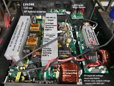
There are three or four thermistors. They are on each heat sink.

You can see three of them in the below picture denoted with the red circles.

Likely 10k ohms @ 25 degs C ntc3950 thermistors.

Each can have different amount of heating depending on power flow. PV SCC to AC out, PV SCC to battery charging, battery to AC output, AC input to battery charging, heats up different heat sinks more or less amount. There are four heat sinks, middle heat sinks in picture are two isolated heat sinks, left heat sink is battery MOSFET, right is PV SCC heat sink.

LV6548 Pict breakdown.jpg
 
Last edited:
There are three or four thermistors. They are on each heat sink.

You can see three of them in the below picture denoted with the red circles.

Likely 10k ohms @ 25 degs C ntc3950 termistors.

Each can have different amount of heating depending on power flow. PV SCC to AC out, PV SCC to battery charging, battery to AC output, AC input to battery charging, heats up different heat sinks more or less amount. There are four heat sinks, middle heat sinks in picture are two isolated heat sinks, left heat sink is battery MOSFET, right is PV SCC heat sink.

View attachment 196477
Wow this is just the information I needed. Thanks for the details and photo to help!
 
Have since discovered that the fans rpm is based on load/amps as opposed to the internal temp of the unit.

Has anyone piggybacked an external fan to the PWM wiring on one of the internal fans? I’m hoping this way as the internal fans ramp up, so would my external fan (and shut down).
 
You might consider a controller that adjust a fan speed based on a thermistor temp which you can attached to heat sinks.

The fan controllers are fairly inexpensive. Find them on eBay, Banggood, and AliExpress.

If the inverter just PWM's the fan speed based on amperage draw without rpm feedback from fan's actual rpm's it's not very reliable for controlling cooling. The three or four wire fans have the rpm feedback. (like used for computer CPU fans).

Heat sinks have a several minute time delay to get hot. Just about the time they are hottest, if the current drops off the fan slows down. Not a great design basing fan speed solely on current level.
 
Last edited:
You might consider a controller that adjust a fan speed based on a thermistor temp which you can attached to heat sinks.

The fan controllers are fairly inexpensive. Find them on eBay, Banggood, and AliExpress.

If the inverter just PWM's the fan speed based on amperage draw without rpm feedback from fan's actual rpm's it's not very reliable for controlling cooling. The three or four wire fans have the rpm feedback. (like used for computer CPU fans).

Heat sinks have a several minute time delay to get hot. Just about the time they are hottest, if the current drops off the fan slows down. Not a great design basing fan speed solely on current level.

Thanks, yes I found another helpful EG6500 thread with similar plans (and link to controller)

I will consider upgrading the internal fans, however my consideration was whether or not I could piggy back an external fan communication somehow so that it runs in tandem with the internal ones.

If not I will go back to my original plan of some kind of temperature activation for the external fan.
 
Back
Top