I just experienced a flakey random no boot failure.. looks like this msb is slightly slower ramp-up 5v on startup..and causing my QT PY to stumble on power up..I doubled up the 10 ohm 5v input resistor .. 2 x 10 =5 ohms.. so far this seems to be enuff to make it stable start up.. I'll keep checking it today.. might have to go to 1 ohm ..hope not..


You are using an out of date browser. It may not display this or other websites correctly.
You should upgrade or use an alternative browser.
You should upgrade or use an alternative browser.
makeSkyBluer
- Thread starter meaCulpa
- Start date
On my breadboard, I retained the 15 ohms and 47uF filter going to the xiao only. I added a series 6.2 ohms and 47 uF filter from the 5V input going to the the OLED display only.I just experienced a flakey random no boot failure.. looks like this msb is slightly slower ramp-up 5v on startup..and causing my QT PY to stumble on power up..I doubled up the 10 ohm 5v input resistor .. 2 x 10 =5 ohms.. so far this seems to be enuff to make it stable start up.. I'll keep checking it today.. might have to go to 1 ohm ..hope not..
so u are already at 5 ohms.. good..On my breadboard, I retained the 15 ohms and 47uF filter going to the xiao only. I added a series 6.2 ohms and 47 uF filter from the 5V input going to the the OLED display only.
I uploaded a new version of the display board that MIGHT have 2 mounting holes in the right places for the msb versions that have the 4 metal standoffs mounting the display board..this will make it a lot easier to mount the display board..if u dont have the black sticky molding version..
ArduinoIDE 2.0.0 is available for download..
Downloading and installing the Arduino IDE 2.0 | Arduino Documentation | Arduino Documentation
A quick guide on how to install the IDE 2.0 on your operative system.
docs.arduino.cc
trying to make doFan() work for PowMr--
void doFAN(){ //FAN control
int32_t x=0;
//Temperature Thermistor
int32_t adc=0;
int32_t a=0;
for(x=0; x<=12; x++){a=analogRead(TEMP_IN);
if(x>=2)adc+=a;}
adc-=adcOFFSET;
adc=adc/10; //divide by 10
// convert the value to resistance
// average = 1023 / average - 1;
float average=adc;
//average=6206/average-1; //MakeSkyBluer 5.0v
average=4096/average-1; //PowMr 3.3v
average = SERIESRESISTOR / average;
//if(Serial)Serial.print("Thermistor resistance ");
//if(Serial)Serial.println(average);
float steinhart;
steinhart = average / THERMISTORNOMINAL; // (R/Ro)
steinhart = log(steinhart); // ln(R/Ro)
steinhart /= BCOEFFICIENT; // 1/B * ln(R/Ro)
steinhart += 1.0 / (TEMPERATURENOMINAL + 273.15); // + (1/To)
steinhart = 1.0 / steinhart; // Invert
steinhart -= 273.15; // convert absolute temp to C
steinhart = (steinhart * 9.0)/ 5.0 + 32.0;
TEMPdeg=round(steinhart);
TEMPdeg+=TEMPvOFFSET;
degHOT=TEMPdeg-ThmStat; //MakeSkyBlue
//degHOT=ThmStat-TEMPdeg; //PowMr
//degHOT=-degHOT; //powmr opposite direction
if((PVv>=BATTv)&&(degHOT>=0)){if(degHOT<=5)fanSPEED="LOW";
if(degHOT>=6){digitalWrite(FANdrv,LOW);
fanSPEED="HI ";}}
if((PVv<BATTv-1)||(degHOT<=-2)){digitalWrite(FANdrv,HIGH); //turn off fan
fanSPEED="OFF";}
}
makeskyblue has the thermistor/resistor from 5v to gnd..
powmr has thermistor/resistor inverted AND betwenn 3.3v and gnd..
Attachments
Last edited:
this looks likeit is working for PowMr--I will continue to test it today..
oid doFAN(){ //FAN control
int32_t x=0;
//Temperature Thermistor
int32_t adc=0;
int32_t a=0;
for(x=0; x<=12; x++){a=analogRead(TEMP_IN);
if(x>=2)adc+=a;}
adc-=adcOFFSET;
adc=adc/10; //divide by 10
// convert the value to resistance
// average = 1023 / average - 1;
// float average=adc;
float average=4096-adc; //powmr/////////////////////////////////////////////////////////////////////
//average=6206/average-1; //MakeSkyBluer 5.0v
average=4096/average-1; //PowMr 3.3v/////////////////////////////////////////////////////////
average = SERIESRESISTOR / average;
//average=average/SERIESRESISTOR;
//if(Serial)Serial.print("Thermistor resistance ");
//if(Serial)Serial.println(average);
float steinhart;
steinhart = average / THERMISTORNOMINAL; // (R/Ro)
steinhart = log(steinhart); // ln(R/Ro)
steinhart /= BCOEFFICIENT; // 1/B * ln(R/Ro)
steinhart += 1.0 / (TEMPERATURENOMINAL + 273.15); // + (1/To)
steinhart = 1.0 / steinhart; // Invert
steinhart -= 273.15; // convert absolute temp to C
//steinhart+=273.15;
steinhart = (steinhart * 9.0)/ 5.0 + 32.0;
TEMPdeg=round(steinhart);
TEMPdeg+=TEMPvOFFSET;
degHOT=TEMPdeg-ThmStat; //MakeSkyBlue
//degHOT=ThmStat-TEMPdeg; //PowMr
//degHOT=-degHOT; //powmr opposite direction
if((PVv>=BATTv)&&(degHOT>=0)){if(degHOT<=5)fanSPEED="LOW";
if(degHOT>=6){digitalWrite(FANdrv,LOW);
fanSPEED="HI ";}}
if((PVv<BATTv-1)||(degHOT<=-2)){digitalWrite(FANdrv,HIGH); //turn off fan
fanSPEED="OFF";}
}
msb V113
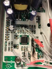
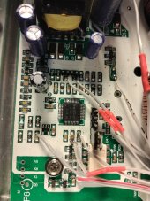
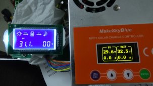
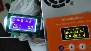
To make sure my PV and Batt analog taps are correct, I connected the keyboard and the xiao pcb analog inputs connector to the msb. I also connected the original LCD display. The xiao outputs are not connected. I did not jumper the Device Reset of the TMS320... So both the TMS320 and the xiao will be running at power on. The pictures show the voltage readings for PV and Batt. Will find out how to calibrate with meaCulpa's code.
And it looks like my taps are reversed. Or maybe not, in this test I used another power supply to the BT+ and BT- connector. I need to use a real battery and repeat this test.
Attachments
Last edited:
looks real good..I cleaned up doFan() and added a new const called 'board' so u can select either MakeSkyBlue or PowMr(v113) and any differences between these models will be selected in code.. like in doFan()..
its already set for ur board..apparently V113 is the same board as PowMr..
to calibrate voltages, start with PV_zero.. supply BATT power but no PV.. and adj PV_zero for 0.0
that establishes basic adc offset for all readings..
then adj CAL_BATTv against a DVM
then CAL_PVv
lastly CAL_PVi (optional) it might be pretty close already..
every time u re-compileand upload it will over-write ur adjusted settings..so write down the values as u cal things and u can put these correct values in the EEPROM routine--the first boot-- settings
Attachments
Last edited:
/mrst the v113 micro and go for it....!!msb V113
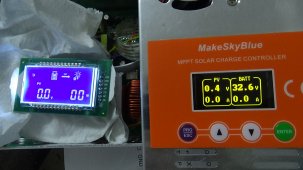
Looks like analog taps are correct. I disconnected the PV inputs and only kept the BT inputs and it showed in the displays.
Hopefully, I will have time tonight./mrst the v113 micro and go for it....!!
at about line 155, u can select board type..PowMr or MakeSkyBlue...
I had to go back to IDE 1.8.whatever.. 2.0 not friendly to me..dont like the pop-ups always in the way and the edit/find gadget is horrible to use..
wonder if others had same bad experience..
latest .ino attached has some cleaned up stuff.. definitely use it for starting place..
I had to go back to IDE 1.8.whatever.. 2.0 not friendly to me..dont like the pop-ups always in the way and the edit/find gadget is horrible to use..
wonder if others had same bad experience..
latest .ino attached has some cleaned up stuff.. definitely use it for starting place..
Attachments
msb V113
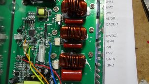
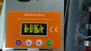
Finally I connected it to a 48V battery pack and a power supply to the PV terminals. Adjusted the gains and I think I got them right. The fan is always on even when i switched the values in the code lines 63 and 64:
#define MakeSkyBlue 0
#define PowMr 1
The NTC terminals read 2.44V and 4.21V, VCC is exactly 5.00V. xiao pin8 (A7) is always at 3.3V. Still troubleshooting.
Attachments
If xiao-A7 is Hi then FanDr has to be LOW.. make sure the fan FET has a LOW at the gate..
I dont understand the 4.21v on the hi side of the thermistor..I'll measure mine tmro..I thot it was 5.00v..
if u forgot to /mrst the v113 micro, the fan might run..
can u do a power scan and jpg it..
I dont understand the 4.21v on the hi side of the thermistor..I'll measure mine tmro..I thot it was 5.00v..
if u forgot to /mrst the v113 micro, the fan might run..
can u do a power scan and jpg it..
msb V113If xiao-A7 is Hi then FanDr has to be LOW.. make sure the fan FET has a LOW at the gate..
I dont understand the 4.21v on the hi side of the thermistor..I'll measure mine tmro..I thot it was 5.00v..
if u forgot to /mrst the v113 micro, the fan might run..
can u do a power scan and jpg it..
I think I made two mistakes:
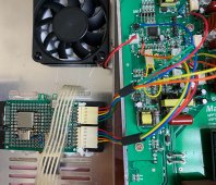
1. Using a 30v power supply connected to BT+ and BT-, no PV power, the high side of the NTC now measures 3.3V and the other side is 1.72V. I don't know why they were reading high last night, will re-do tonight. Tracing the pcb, the 3.3V comes from pin 11 of the tms320, per datasheet, Pin 11 is VDDA (3.3V).
2. On my breadboard, I incorrectly substituted non-inverting buffers (74LVC2G34) for your inverting buffers (74HC14). Will add an inverter to the fan drive signal path. I think I am ok on the pwm signal paths. Will test tonight.
The connector with the yellow loop wire is the /mrst jumper in the picture.
Attachments
pwm drive will also need to be inverted..not just the fan drvmsb V113
I think I made two mistakes:
1. Using a 30v power supply connected to BT+ and BT-, no PV power, the high side of the NTC now measures 3.3V and the other side is 1.72V. I don't know why they were reading high last night, will re-do tonight. Tracing the pcb, the 3.3V comes from pin 11 of the tms320, per datasheet, Pin 11 is VDDA (3.3V).
2. On my breadboard, I incorrectly substituted non-inverting buffers (74LVC2G34) for your inverting buffers (74HC14). Will add an inverter to the fan drive signal path. I think I am ok on the pwm signal paths. Will test tonight.
The connector with the yellow loop wire is the /mrst jumper in the picture.
Attachments
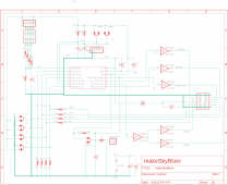
In your schematic, if A8(74HC14-1) is plus, 74HC14-2,3,5 are minus. 74HC14-4 (PWM1) and 74HC14-6 (PWM2) are plus. So effectively, no inversion. I followed the same two buffers in series scheme. But for the fan drive, no series buffers.pwm drive will also need to be inverted..not just the fan drv