diy solar

diy solar

Modbus Register Backflow Power for Solis Hybrid Inverter

the biggest culprit to me sounds the meter placement.
in have set it to ‘Pv inverter’. I think it must be set to ‘grid’, where indeed the meter is located. indeed the acres meter is at the same location as the sma energy Meter and both are directly behind the main grid fuses .

my acrel-meter indicates positive values when we export into grid.
OK, if the meter is on the grid side, the inverter should be set to "meter placement: grid".
It is better to test this at night so the other SMA inverters will not interfere (or switch the SMA off).
If polarity of power is wrong you can change "CT direction" in solis options to reverse it.
The result should be: at night, running from battery, Solis inverter adjusts its output power to compensate for power used by the house, like this:
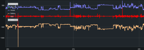
1685272034791.png

So this should fix your oscillation problem, I hope.

Now since you use other inverters with AC coupling, there's a bit more configuration. We don't have the same Solis model (I have S5) but perhaps yours will behave in a similar manner. Basically my Solis inverter doesn't like to see export power reported by the meter to be higher than the "backflow limit" setting. If this happens for more than a couple tens of seconds, it will shut down. Thsi happens if the other AC coupled inverters output more power than what the house is using, which results in net export. The solution is to increase the "backflow limit" setting, then it works fine.

I see a 3 phase Acrel meter on the picture, note I don't have code for this one, I sent you the code for single phase Acrel.
 
Dear Peufeu,

the setting to grid is giving me pain..

If I set the meter to "PV Inverter", then the Solis reports nicely that RS485 towards the meter is "OK". With that setting I am seeing each Phase Voltage and Ampere.

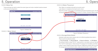
The Meter itself (or better said the CT-clamps) look correctly installed, as the snippet from Manual reflects how I am seeing it:
- when exporting into Grid, the Smartmeter shows positive values
1685277134626.png

However once I change setting to "grid", then the Solis sounds to loose connection to the meter.

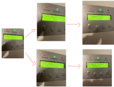
I have made a drawing to show the difference.

Setting the CT-install to Grid, Meter-Status goes to Null
Only in Setting PV-Inverter the meter-status is ok.

Wondering myself if I am doing something really stupid wrong here..

1685277372107.png


Basically my Solis inverter doesn't like to see export power reported by the meter to be higher than the "backflow limit" setting. If this happens for more than a couple tens of seconds, it will shut down.
[christian] thanks for note. I am not facing this issue. But good to be aware. backflow-limit is set to zero.


If polarity of power is wrong you can change "CT direction" in solis options to reverse it.
[christian] Could not spot this menu-item in the Solis. But I reversed the clamps. The Energy-meter indeed then indeed shows all reversed, however its not helping with mine issue, that once I change the menu for "Installed CT on" from Grid to "PV Inverter", then the RS485 towards the Acrel Energymeter goes down.


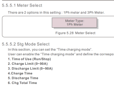
What confuses me, is the fact that my Solis has only a setting for the CT. But in Reality is should be the meter-setting as shown here from the manual:

1685278288393.png

But this menu-item is not available in mine Solis. Tried it a couple of times..

thanks
 

Attachments

  • 1685278184640.png
    1685278184640.png
    224 KB · Views: 5
ah, feeling somewahat stupid. Indeed this is the correct manual. thanks for sharing.
The CT could be used to measure PV-power. But as only one CT can be attached at all and I have PV-power on all 3 phases, I have not attached it.
Maybe I should give it a try..
1685280774682.png

If the meter shall work, then only the "PV-Inverter"setting does the job. Still confusing to me, as I have not attached the CT at all.

1685280471300.png

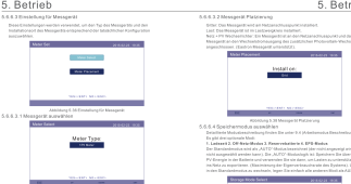
And indeed the manual confirms that I there is no "grid"setting for the meter..

1685280568549.png


as a next step let me see if I can get the CT-clamp attached.

thanks
 
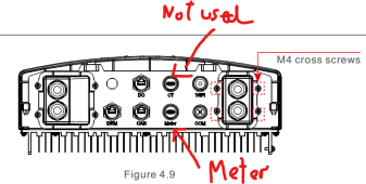
So you have external CT, mine has an internal CT. I think this CT is used to monitor the inverter's own output power.

You can check if it displays correct information, the manual shows this on "Figure 5.9 Information list (CT Infomation)"

Maybe it needs it for its control loop...
 
@peufeu - just wanted to say thanks for creating the grugbus code and publishing (and documenting it pretty well as well !!)

I have a bit of a different config (i am in Australia) - 1 have 2 x 3 phase Solis inverters - one is called a 3Phase - 4G-5K (5 Kilowatt 4th Generation) it is not a Hybrid. I have a 2nd unit which is also 3 phase which is Solis 25K (this was how it was first named before they bought in different generations etc) and is a 25kw 3 phase unit.

Our power company provides us with wholesale rates so often during the middle of the day our price to feed power to the grid will go into negative. (i.e. we are paying to feed power to the grid)

I have a couple of goodwe inverters as well with batteries attached and can command them through modbus to charge and discharge - however once they are full we then want to scale back the output of the Solis inverters so that they are only offsettting the house load not sending any extra to the grid.

We have an Eastron 630 meter on the grid feed line - but this is not supported directly by these inverters - they only support the ACREL DTSD1352 (3 phase) which i do not have - but do have the Modbus registers for.

If i created a Grugbus unit from a spare PI i have and a Modbus register map for the 3 phase ACREL meter i assume i would be able to use Grubus to push any fake information i want back to the meters ?

I am trying to work out which modbus maps are the correct one for my inverters as there seem to be two main ones out there - one for the hybrids and another for the non-hybrids

Craig
 
I tested out what you said this morning with mixed results. It seems that because I had a discharge time slot set that was the reason why the inverter exported the "back flow" power to the grid regardless of battery SOC. So I understand that a lot better now. Thank you ! The solis manual is just so bad !
But I found that when I set no discharge time slot the grid import/export becomes quite erratic..... certainly not as stable as in your figure above.
View attachment 141206
This is a trace from testing this morning. I disabled the discharge timeslot between 10am to ~10:40am. Battery was not fully charged so I had expected the export to go to a stable zero. But you can see it is just all over the place. This trace is at 1min timestamps, the 5sec measurement on the inverter screen was all over the place. Clouds were very intermittent this morning so the power was surging to the panels which was maybe giving the control loop a hard time, or maybe this is to do with the distance between my CT clamp and inverter which is a good 20m ?

But there is another disadvantage to this. If I could get this more stable, when the inverter tries to export 0W there is always a small residual grid import, either due to CT clamp noise or inverter control loop tolerances. Its not much but I have found it adds up to ~0.5kWh per day which over a year is ~£100 on my current tariff. So I set the backflow power to a low 100W which ensures no grid export. You can see it in the figure above. So for me programming export on Modbus makes more sense when my battery is full so I can keep the residual backflow power of 100W.
Firstly, distance from CT to whatever its connected to is not an issue; the only thing which would cause problems would be poor insulation between the two cores - not going to happen with a modern cable.
Second, my (dealer-installed) Solis hybrid inverter type RHI-5K-48ES-5G (v1) has the CT connected to a DIN-mounted power meter which then has an RS485 modbus connection to the inverter. The fastest the inverter could sensibly be reading the CT current/phase would be of the order of four times per second - perhaps ten if you're lucky. This means the inverter has no chance to respond on a cycle-by-cycle basis as it could if the CT was connected directly to the inverter.
Some other vendors' inverters (e.g. Tesla PowerWall) take a CT connection directly, without going through the intermediate power meter module. This allows them to do almost zero 'accidental import/export' as the load changes. I don't think my Solis has this facility.
 
...
Second, my (dealer-installed) Solis hybrid inverter type RHI-5K-48ES-5G (v1) has the CT connected to a DIN-mounted power meter which then has an RS485 modbus connection to the inverter. The fastest the inverter could sensibly be reading the CT current/phase would be of the order of four times per second - perhaps ten if you're lucky.
In theory the meter can respond that quick, but the Solis will only read an Eastron meter every 2s or an Acrel meter every second.

I don't think my Solis has this facility.
That is correct.
 
This allows them to do almost zero 'accidental import/export' as the load changes.
I think it’s more accurate to say that it’s not as inherently slow as going through a meter that adds it’s own latency.

But there’s no guarantee that the zero export software responds with super low latency. In fact that would be harder to implement and not necessary to do so in many approved zero export setups.

And IMO there are very few manufacturers that would do the extra engineering to get as close to instantaneous zero export as possible if they are allowed to average it out over a few seconds for approved setups.
 
And to add what @zanydroid said... in my experience the zero export issue is not down to the actual reading of the meter vs. CT clamp. My Solis reads its Acrel every second, but when you switch on (or off) a big load it takes many seconds for the Solis to ramp up or down its solar production and/or draw from the battery. So even with sampling every second there is always a few seconds of import when a big load goes on and the same in reverse (i.e. an export) when a load switches off.
 
I went up the thread to see the context for the question. The extra spurious export and consumption is still better than not controlling it. Assuming you have no bugs in the implementation.

FWIW if you add an AC battery to absorb (using its zero export logic) that would also help, and you would as well not “waste” the production. I think for instance LuxPro sells one in 230V territories (I believe at a lower cost than powerwalls) though this is an increasingly popular product so I’m sure there are other vendors.
 
@peufeu
If i created a Grugbus unit from a spare PI i have and a Modbus register map for the 3 phase ACREL meter i assume i would be able to use Grubus to push any fake information i want back to the meters ?
Sorry I don't remember if I answered this in another thread.
Answer is yes, but you're not pushing the fake info to the meters, but to the inverters.
 
I went up the thread to see the context for the question. The extra spurious export and consumption is still better than not controlling it. Assuming you have no bugs in the implementation.

FWIW if you add an AC battery to absorb (using its zero export logic) that would also help, and you would as well not “waste” the production. I think for instance LuxPro sells one in 230V territories (I believe at a lower cost than powerwalls) though this is an increasingly popular product so I’m sure there are other vendors.

If you have a hybrid inverter then you need to control it (even with spurious bits of transient export) otherwise you'll just discharge the battery by exporting too much all the time... in fact when PV is producing, if it didn't measure import/export power and react to it, it couldn't decide between charging the battery or pushing energy into the grid to compensate for what the house consumes.

I believe most of these batteries also use smartmeters, so there will always be a little bit of delay and transient spurious import/export. It's not important.

In fact if you have a "solar" EVSE for the electric car, you get an extra smartmeter (obviously their own, gotta be incompatible with yours) and then they all have to figure out what to do with the watts, and how these feedback loops interact is... the user's problem ?
 
I believe most of these batteries also use smartmeters, so there will always be a little bit of delay and transient spurious import/export. It's not important.
A lot of the ones in the US have built-in CTs. The remote CTs (either analog or connected via meters) are used for more complex cases.

Yeah, I have no idea what's going to happen if you have two zero export control loops that don't know about each other. Probably not what you want. In general energy management systems aren't very easy to compose/customize right now.

You can potentially use a RS485 proxy to allow multiple things to talk to one meter but that only makes the setup "neater", it doesn't fix the problem with two non-coordinated control loops.
 
You can potentially use a RS485 proxy to allow multiple things to talk to one meter but that only makes the setup "neater", it doesn't fix the problem with two non-coordinated control loops.
Yes - you'd have to write the co-ordinating logic in your RS485 proxy.
 
Not specifically for that AFAIAA, but check out @peufeu's github project for MITM comms for Solis inverters. A variant of that could be used to co-ordinate devices, assuming they expose such control via their ModBus interefaces - see posting #23 of this thread.
 

diy solar

diy solar
Back
Top