You are using an out of date browser. It may not display this or other websites correctly.
You should upgrade or use an alternative browser.
You should upgrade or use an alternative browser.
Mounting BMS to case
- Thread starter hardtop
- Start date
One thing that you might consider is wood deformation with pressure and time. Four lengths of all thread and springs are a well accepted method. However the use of a single piece of 3/4” ply will eventually bend with either fixed or with compression forces allowing the end cells to deform. I found that at least two pieces of 3/4” ply laminated with Tite Bond 3 glue greatly reduced the bowing.
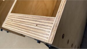

If your cells are bending 3/4 ply in a 4s configuration, either you have junk cells that expand way more than they should or are pre-compressing the heck out of them.
If it were one string of 16s, that might be a different story.
If it were one string of 16s, that might be a different story.
If you are using a single 3/4”, good quality plywood end plate and it
If you’re using a single 3/4” good quality ply and you have it spring compressed at 10 psi (550 lbs total), you will bend the board. You either haven’t noticed, don’t have correct compression or don’t have enough months on it. That goes for CATL or Eve cells. I’m running 8 cells in a fixture (6 fixtures.) From a cool day, low charge to a hot day full charge there is a 3/16” difference in fixture length (end plate travel) that means each cell is expanding .023” despite being under compression. Would the wood bend be less with 4 cells? Perhaps, but the pressure is close to the same IF it’s sprung with reasonable spring travel and not a rigid.If your cells are bending 3/4 ply in a 4s configuration, either you have junk cells that expand way more than they should or are pre-compressing the heck out of them.
If it were one string of 16s, that might be a different story.
curiouscarbon
Science Penguin
- Joined
- Jun 29, 2020
- Messages
- 3,024
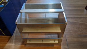
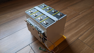
spiffy!!!!I drilled and tapped the edges of the heat sink and used 1/2" (12mm) aluminum angle to mount the BMS. That also gives me a bit more heat dissipation through the aluminum compression frame.
View attachment 191261
View attachment 191262
very nice looking build
rigid and heat conducting, although little conduction path to frame, with rigid insulator between cells, and compressible electrical insulator between cell and frame, nice.
may i ask about the short face between cell and frame? no insulation seen there. cell on either end should be prevented from lateral movement, but inner two cells seem to have less fixing force from smooth (fiberglass?) separator. cannot see significant abrasion wear potential for those, but maybe slightly more than outer cells.
may i ask whether rigid or flexible cell interconnect will be used?
definitely looks more sturdy and compact than what i have planned
thank you for sharing!
This was a lot of work. I can’t see any isolation on the sides and if you haven’t left room for it, not to worry. Aluminum can be hard anodized. Hard anodizing is one of best insulator known for its thickness and incredibly durable. The anodizer needs to know what alloy the parts are made of and I would recommend that you callout for having all taped holes masked.I drilled and tapped the edges of the heat sink and used 1/2" (12mm) aluminum angle to mount the BMS. That also gives me a bit more heat dissipation through the aluminum compression frame.
View attachment 191261
View attachment 191262
Edit: Inquire as to what sealing options the anodizer has on facility. Recommend doing this to help keep it stay cleaner and allow cells to glide and not stick and damage cell coverings.
Last edited:
hardtop
New Member
That box looks sweet. This summer I'm going to be needing heat dissipation since it gets 115F and there isn't an A/C for the battery pack unless I drive around with it lol. I haven't experienced that heat yet with my DIY pack. I hope to god it doesn't just burst into flames like an RV on the side of the road.
Oh, boy. You post a few photos to answer the question at hand, and the conversation immediately changes!
The sides and bottoms of the cells are insulated with Kapton tape. I started out using black electrical tape but finally just bought a roll of 2" Kapton. It works well. This box has been in service now for about six months at a remote site and seems to be doing very well. I had to crawl in and change it to add the data port and remove the Bluetooth dongle you see in the photos. I now have a microcontroller logging data and emailing it to me via the neighbor's WiFi (with his permission).
Anyway, the box is primed and painted. Those are FR4 separators and the compression is provided by a 1/4" sheet of Poron foam. I measured the poron compression per distance and built the box to provide that thickness. That is all reported in the Poron foam thread. Bus bars are flexible. BMS leads are attached via 1/4" spade terminals soldered to the bus bars. The 250A Class T fuse mounts on the front panel, and the battery leads connect to an Anderson connector. I printed a red cover to make sure I don't drop anything in there if I have to open it up.
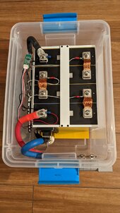
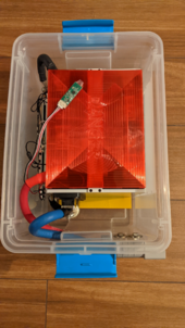
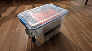


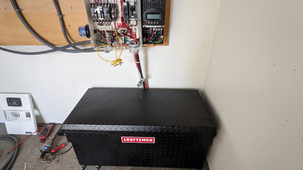
That box was the proof of concept for the 16S2P battery that I made for the main power. The boxes are narrow enough that a flexible bus bar will reach across the edge to the next box over. I can't lift over 8 cells at a time, so I wanted a way to make 16S with two 8 cell boxes. Note the top bar colors in the photo; left side is the "silver" battery, right side is "gold." It all fits inside a Craftsman truck bed box. The hole in the cover panel allowed me to reach in and connect the negative cables to each battery. The red covers went on as I connected things to help avoid that oops moment we all fear.
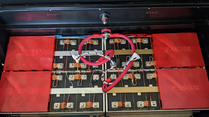
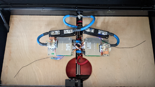


Similar threads
- Replies
- 35
- Views
- 902
- Replies
- 3
- Views
- 466
- Replies
- 3
- Views
- 358


