jester74
New Member
- Joined
- Jun 13, 2022
- Messages
- 6
Hi all!
Long-time lurker, first time posting. First of all, thank you to all contributors here, I've learned a TON. Truly appreciate the shared knowledge.
My current question:
I have an EcoFlow Delta mini which I hope to as a UPS strictly for my fridge (typically 70 watts, no more than 500w when using ice-maker heat strip), a small freezer (about 150 watts) and minimal electronics (router and NAS another 150 watts). The Delta runs them fine when plugged directly in to the unit.
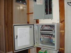
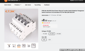
I have read just about every thread regarding the nightmares of using portable power stations as a parallel-to-grid UPS (or EPS) where the portable power station is plugged to the inlet of a transfer switch that typically does not switch the neutral wire, which then clashes with the neutral feeding the AC-in of the PPS and things trip, give errors or release smoke.
My idea around this is the following:
What if at the main panel I completely remove the romex going to my critical loads (confirming there's only one outlet per each circuit... the kitchen fridge, the garage freezer, and the router/NAS outlet) and instead terminate them at three separate 120v male inlets immediately outside/beside the main panel? Basically turning those three circuits into code-friendly in-wall romex extension cords. I could then plug those inlets to the Delta while the Delta itself is plugged in to a separate circuit from the grid. This would make it so there's zero chance of neutral loops, and would still let me have GFCI outlets (not breakers) at the fridge and freezer (though I'd have to use an adapter to connect the plug's ground at the Delta's AC out to actual ground since it only has a dummy hole for ground). If the inverter ever needs to be removed from the picture temporarily, I could plug in cords from those inlets to separate nearby outlets fed from the main panel and thy'll be back in business, and of course, reverting back permanently would only require running the romex back to the main panel and removing the inlets.
I would label the outlets by the three circuits with something clear, such as "This outlet is fed from Main Inlet 1 next to Main Panel in Garage" etc. And "Inlet to feed Kitchen Refrigerator outlet" etc. at the appropriate inlet. Maybe use different-colored outlets, like hospitals do?
Any flaws in this approach? Do you see any code violations? Although I only plan to have one outlet per "extension", would having more than one outlet on the same extension circuit be allowed since the Delta can't put out more amps than the romex is rated for?
There's more to the plan, but I didn't want to make this too convoluted, but ask away if necessary.
Thanks in advance!


