diy solar

diy solar

Use Main Panel as Critical Loads Panel?

lapsmith

New Member
Joined
Apr 10, 2022
Messages
234
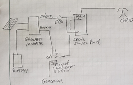
Is there anything wrong (i.e. against any code) with feeding the output of a grid tie inverter (Growatt MIN144000TL) back to the main service panel through a "generator" circuit breaker and a manual* transfer switch? The circuit breaker would be interlocked with the main breaker of course. The Growatt backup output is 25 amps, 240V max.. I can't see anything bad happening because the transfer switch would be off, except during a power outage. This would mean I wouldn't have to install a separate critical loads panel (which I would manage manually anyway).

*I don't want automatic transfer because some loads would kill the backup battery, but are still needed occasionally. For example the aerobic septic system. If the power goes out I don't want the septic system aerator to be on 24/7. I want to control it manually to conserve battery life.
1703710910395.png
 
I would think you still need a way to isolate the main panel from the grid if you are backfeeding to the main panel. I appreciate it is manual transfer. prob would still require an way to ensure the grid is locked out when you engage the genny. I would think the whole system would need to lock out all production (Genny/battery/PV) to keep the grid system separate during a grid down event. You mention interlock. I assume that the device would do this.

I am sure someone on the forum has a similar set up and will provide input :)
 
Yes, using a breaker interlock system is a common way to power a main panel with multiple sources and should meet code in most places. The issue is with the AC Disconnect on the Inverter AC Input. If you forget to open this switch when using inverter as back up, a current loop is created. Not sure what bad consequences may occur or if it would pass code. Even if you are careful, there is always the argument, what if someone else tries to use the system?

Wonder if your manual transfer switch has any aux contacts? If so you may be able to use a remote trip breaker instead of a disconnect. Then route power through the aux contacts which will trip the breaker to the inverter AC input. Maybe over complicated but a little safer.
 
I would think you still need a way to isolate the main panel from the grid if you are backfeeding to the main panel. I appreciate it is manual transfer. prob would still require an way to ensure the grid is locked out when you engage the genny. I would think the whole system would need to lock out all production (Genny/battery/PV) to keep the grid system separate during a grid down event. You mention interlock. I assume that the device would do this.

I am sure someone on the forum has a similar set up and will provide input :)
He did mention using an interlock between the main and the Gen input breaker.
 
The separate AC disconnect is a bad idea as others mentioned, you need to interlock it correctly.

EDIT: OK, your text has interlock but it's not in the diagram. Reading is hard :laugh:

Another way to do this is to use the ATS (which is required, it provides the neutral forming), but have a transfer switch / critical loads panel with per-circuit transferring etc downstream of it to pull in the circuits that you might need. This also deals with the AC disconnect problem because the ATSUS handles this.

Then the system will both work correctly (because the Growatt really needs this ATS) and you get the ability to pull things in manually.

Does the Growatt not have the ability to connect a generator? If so, that really sucks in combination with the HV ARO battery, because if it was 48V you could have DC coupled in a generator via a chargeverter ?. Maybe there's a way to switch the generator in via the Grid input to the inverter. But you would still need to be careful if the Growatt does not have a setting for capping the input current.
 
If you're trying to keep this very simple and don't care about anything switching automatically, Just buy an Interlok kit as you indicated. You can wire a separate 30amp L14-30 outlet box from the inverter along with a generator inlet box by the main panel. If/when power goes out, plug the "generator" cable to the respective outlets and throw the Interlok on the main panel. That's how I set mine up.
 
If you're trying to keep this very simple and don't care about anything switching automatically, Just buy an Interlok kit as you indicated. You can wire a separate 30amp L14-30 outlet box from the inverter along with a generator inlet box by the main panel. If/when power goes out, plug the "generator" cable to the respective outlets and throw the Interlok on the main panel. That's how I set mine up.
This is an inherently non-simple setup because of the inverter used in the project.

This model of inverter (240V AC output, no neutral by itself) needs an automatic relay to switch to Auto Transformer relay anyway. It's mechanically or electrically interlocked with the automatic switch on L1/L2 because you can't parallel the neutral output from an auto transformer to the grid while using on-grid power (code violation and causes the auto transformer to fight the utility transformer)
 
because you can't parallel the neutral output from an auto transformer to the grid while using on-grid power (code violation and causes the auto transformer to fight the utility transformer)
You can, it's not a code violation. In fact, if the autotransformer is connected to the grid. The neutral must also be connected to the grid.
They don't fight each other. They help each other, because they are in parallel with each other.
But this configuration can be troublesome. If the grid transformer also feeds your neighbors house. Because your autotransformer could get overloaded.
Thanks for the correction. What is the definition of connected to the grid? (presumably the way the transfer switch is internally wired in the accessory, does the right thing to disconnect it) Anyway, it doesn't really matter because the Growatt ATSUS accessory that embeds the autotransformer is UL listed so you can wash your hands of it if you follow the wiring diagram /s

What happens if the autotransformer is a couple volts off from the grid transformer? From leg imbalance voltage drop or manufacturing variation. How does it not fight in this case? There would be extra neutral current, on the neutral and on the windings, to bridge the voltage difference.
 
What happens if the autotransformer is a couple volts off from the grid transformer?
I don't see how it could be. It just takes the available voltage (whatever it is) and creates a center tap.
How does it not fight in this case?
They just balance out. It's no different than two batteries in parallel.
Voltage is the great balancer for everything.
 
I don't see how it could be. It just takes the available voltage (whatever it is) and creates a center tap.
Let's say the Utility transformer is wired 51/49% of the way from L1 to L2

And the autotransformer is wired at 49/51% between L1 to L2

L1-L2 is 240V in both cases. The autotransformer neutral would be at about -5V in this case relative to the ground bond at the utility side.

Two batteries in parallel at different voltages is not good, I think that is the equivalent situation.
 
Let's say the Utility transformer is wired 51/49% of the way from L1 to L2

And the autotransformer is wired at 49/51% between L1 to L2

L1-L2 is 240V in both cases. The autotransformer neutral would be at about -5V in this case relative to the ground bond at the utility side.
If the windings are not perfectly tapped in the center. It won't cause any issues. But efficiency will suffer a little. Because the unbalanced load will be balanced twice.
 
I can't think of a way to answer without sounding like a smart ass.
So please don't take it that way.
Connected is connected.
Well the context of the question, if you have a relay-controlled AT neutral output. Does L1/L2 of AT need to be disconnected from grid, when the neutral is disconnected by the relay from the circuit. Or can L1/L2 still be connected to the grid, because the neutral isn't doing anything (IE the AT is nothing but an inductor). One argument to add a 3-pole interlocked disconnect is that it will avoid burning some power cycling reactive power through the unused transformer.
 
Two batteries in parallel at different voltages is not good, I think that is the equivalent situation.
True, probably not the best comparison.
Because both batteries are power sources. But both transformers are not.
The autotransformer is just reacting to the situation presented to it.
 
Well the context of the question, if you have a relay-controlled AT neutral output. Does L1/L2 of AT need to be disconnected from grid, when the neutral is disconnected by the relay from the circuit. Or can L1/L2 still be connected to the grid, because the neutral isn't doing anything (IE the AT is nothing but an inductor). One argument to add a 3-pole interlocked disconnect is that it will avoid burning some power cycling reactive power through the unused transformer.
You can disconnect all 3.
Or just L1 and L2.
Or just the neutral.
You just can't use the autotransformer neutral for loads, unless it's also connected to the neutral of the feeder. if the feeder comes from a system that has a neutral. (Split-phase or 3-phase Wye systems)
 
You just can't use the autotransformer neutral for loads, unless it's also connected to the neutral of the feeder. if the feeder comes from a system that has a neutral. (Split-phase or 3-phase Wye systems)

The ATS output neutral in the Growatt schematic is connected to a common neutral bar with the feeder. And then the CLP's neutral hangs off this.
 
Well the context of the question, if you have a relay-controlled AT neutral output. Does L1/L2 of AT need to be disconnected from grid, when the neutral is disconnected by the relay from the circuit. Or can L1/L2 still be connected to the grid, because the neutral isn't doing anything (IE the AT is nothing but an inductor). One argument to add a 3-pole interlocked disconnect is that it will avoid burning some power cycling reactive power through the unused transformer.
I leave my L1/L2 autotransformer connected to the grid without its neutral, it appears to draw about 30W doing nothing last time I checked.
 

Attachments

  • Screen Shot 2023-12-27 at 6.40.20 PM.png
    Screen Shot 2023-12-27 at 6.40.20 PM.png
    144.8 KB · Views: 12
This is an inherently non-simple setup because of the inverter used in the project.

This model of inverter (240V AC output, no neutral by itself) needs an automatic relay to switch to Auto Transformer relay anyway. It's mechanically or electrically interlocked with the automatic switch on L1/L2 because you can't parallel the neutral output from an auto transformer to the grid while using on-grid power (code violation and causes the auto transformer to fight the utility transformer)
Agreed. Completely missed the grid-tied wording.
 
Back
Top