diy solar

diy solar

18kpv with critical loads backup panel - does it really need a 70a subpanel breaker?

nuke

New Member
Joined
Jun 28, 2023
Messages
110
Location
San Jose, California
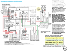
Per this diagram, they state that the critical loads subpanel breaker must be no bigger than 70 amps. I don't get why - as long as the critical loads subpanel is rated for 200a, and the wiring from the 18kpv to the critical loads subpanel can support 200a, won't it be fine?

My reasoning:
1) My critical loads subpanel right now is a 225a bussed MLO panel that I don't want to replace since it has a lot of breaker slots
2) Theoretically, the inverter + main loads panel could provide over 100a to the critical loads subpanel together, so why limit to 70a if the wiring and panel supports it?


1702762489153.png
 
Last edited:
The internal circuitry can't handle it. If you don't protect it properly, you will fry it.

Edit: I see now that you are talking about the grid feed in.
It's the 120% rule. This is to keep from melting the bus bars in your main panel.
 
Last edited:
Per this diagram, they state that the critical loads subpanel breaker must be no bigger than 70 amps. I don't get why - as long as the critical loads subpanel is rated for 200a, and the wiring from the 18kpv to the critical loads subpanel can support 200a, won't it be fine?

My reasoning:
1) My critical loads subpanel right now is a 225a bussed MLO panel that I don't want to replace since it has a lot of breaker slots
2) Theoretically, the inverter + main loads panel could provide over 100a to the critical loads subpanel together, so why limit to 70a if the wiring and panel supports it?


View attachment 183398
It doesn't make sense to me either since the 18kpv supports 200 amp bypass. Why should the input be limited by a 70 amp breaker?
 
It doesn't make sense to me either since the 18kpv supports 200 amp bypass. Why should the input be limited by a 70 amp breaker?
It’s to protect the main panel. If you want the full 200a through it, put the 12k/18kPV between meter and main panel. Your main panel is then a critical loads.
 
The internal circuitry can't handle it. If you don't protect it properly, you will fry it.

Edit: I see now that you are talking about the grid feed in.
It's the 120% rule. This is to keep from melting the bus bars in your main panel.
The main panel will still have a 70a breaker feeding the GRID input of the 18kpv.

I'm talking about the breaker size on the critical loads panel.
 
It doesn't make sense to me either since the 18kpv supports 200 amp bypass. Why should the input be limited by a 70 amp breaker?
Right - And even to the extent that i'll never see 200a at the critical load panel input, I don't get why I have to limit it just because i'm using a backfeed breaker at the main panel versus a line side tap
 
The main panel will still have a 70a breaker feeding the GRID input of the 18kpv.

I'm talking about the breaker size on the critical loads panel.
The critical loads panel breaker size is determined by the output limit of the gen port. I'm not sure what that is. Maybe it's 70a?
 
Unless you are connecting your "critical loads panel" to the loads port. Then it can be whatever you want it to be. As long as the wiring is sized correctly.
The only limit is the pass through and inverter output.
70a + 50a = 120a
 
Unless you are connecting your "critical loads panel" to the loads port. Then it can be whatever you want it to be. As long as the wiring is sized correctly.
The only limit is the pass through and inverter output.
70a + 50a = 120a

Right, I was going to connect it exactly like in the picture above (to the LOAD output), and run my enphase crap to the GEN input. GRID would be from a 70a backfeed breaker at the meter/main.
 
Right, I was going to connect it exactly like in the picture above (to the LOAD output), and run my enphase crap to the GEN input. GRID would be from a 70a backfeed breaker at the meter/main.
I don't see any problem with that.
Assuming that you have already confirmed that your main panel can support 70a.
 
Per this diagram, they state that the critical loads subpanel breaker must be no bigger than 70 amps. I don't get why - as long as the critical loads subpanel is rated for 200a, and the wiring from the 18kpv to the critical loads subpanel can support 200a, won't it be fine?

My reasoning:
1) My critical loads subpanel right now is a 225a bussed MLO panel that I don't want to replace since it has a lot of breaker slots
2) Theoretically, the inverter + main loads panel could provide over 100a to the critical loads subpanel together, so why limit to 70a if the wiring and panel supports it?


View attachment 183398
70A is to the main panel in that diagram, not the Critical Loads Subpanel. Misprint?
 
Per this diagram, they state that the critical loads subpanel breaker must be no bigger than 70 amps. I don't get why - as long as the critical loads subpanel is rated for 200a, and the wiring from the 18kpv to the critical loads subpanel can support 200a, won't it be fine?

My reasoning:
1) My critical loads subpanel right now is a 225a bussed MLO panel that I don't want to replace since it has a lot of breaker slots
2) Theoretically, the inverter + main loads panel could provide over 100a to the critical loads subpanel together, so why limit to 70a if the wiring and panel supports it?


View attachment 183398
The 70A breaker in the main panel has to do with the NEC rules on how much power can be put into the main panel. It is sometimes called the 120% rule and states that the sum of all input breakers must be equal to or less than 125% of the busbar rating of the breaker box. (Keep in mind that a hybrid inverter can back feed the main panel)

If the main panel has busbars rated for 225A, the total current for input breakers must be 1.25 x 225A = 270A. Since the main breaker is 200A, the inverter backfeed breaker can only be 70A.

The diagram referenced assumes the sub-panel is powering a subset of the loads that is well under the 200A passthrough capability of the inverter. Other diagrams in the manual show the full 200A passthrough but to get around the 120% rule the inverter ties in *before* the main panel.

The 60A main breaker in the sub-panel is a different story. If the main breaker in the sub panel is 200A, it would never trip. Even if the inverter pumps its full 50A at the same time there is 70A from the main breaker panel, it is only 125A. So.... a 200A breaker could be used as a switch for de-energizing the panel but does not offer any additional over-current protection.

The question becomes: "What does the code allow?" and I don't know if the code requires a smaller breaker there. If it does, you might not be able to find a 60 or 70A main breaker that fits the panel. In that case, just abandon the main breaker in the sub panel and use a 60 or 70A dual pole breaker in one of the load slots.
 
In this case the main sub panel breaker can be anything you want. As long as the bus bars and feeder conductors are rated at or higher.
Actually, as long as the feeder is protected elsewhere. It's size can be based on that protection device.
 
Actually, as long as the feeder is protected elsewhere. It's size can be based on that protection device.
In this case does the 200a load breaker in the 18kpv qualify?

To me it seems that running 3/0 from the 18kpv to the critical load main-lug-only subpanel would reflect the 200a load breaker minimum wire size
 
In this case does the 200a load breaker in the 18kpv qualify?

To me it seems that running 3/0 from the 18kpv to the critical load main-lug-only subpanel would reflect the 200a load breaker minimum wire size
Correct
 
But the 70A breaker in the main panel puts a limit to the amount of current that would ever be allowed through the inverter. The most you would ever see coming out of the inverter is the 70A from the Main panel plus 50A from the inverter. The 200A breaker in the inverter is essentially just a switch.
 
Back
Top