


SparkyGriswald
New Member
Hi wizards, very thankful for all of the wisdom in this community. I live in an area where we do not see too many solar installs. Initally we were going to use a solar installer but communication delays won out - so DIY is the way. I am preparing to submit plans to inspection office.
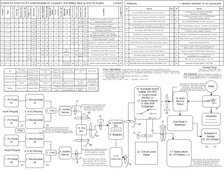
How does this single line diagram look? What changes would you make? I will be erecting a pergola around a pool and the panels will be atop the pergola. Several components already purchased for this system 9.28kW PV DC 6.9kW MI AC PV to Microinverter AC Coupled 5.1kW Battery Back up Grid Tie System - REC PV, M215 MI, Schneider XWPro, EG4 LFP battery.
Specific questions...
1. On my Main panel the last 2 slots on both sides would house a 60A dual pole breaker on one side and 100A dual pole breaker on the other side. Is that a problem or shall I move the 100A breaker (feeder for a subpanel) to a different position? My panel has a "sum of qt breaker rating is not to exceed 110 amps per branch circuit bus stab" limit on it. However the QTs are the tandem breakers (not the dual poles that are planned) - so I am not clear on if it would apply to two dual poles across from each other.
2. For calculations of ampacity - is a Temp derate > 1 actually used in calculations? Or only when the derate is < 1.0? (this would come into play with ampacities in my basement where the T derate >1).
3. My critical loads panel would be fed by 6 AWG from a 60A breaker on the Hybrid inverter. My initial plan would be to have the CLP be a MLO - so 6AWG directly to the CLP - or would you change it to a 60A MB - but I do not think that that 60A breaker for the panel exists - only a regular Dual Pole 60A. Could you use that 60A breaker as the first breaker (slots 2 and 4) on the bus as a feeder for the lower Critical loads? Also is there a limit on the number of Critical loads circuits you can place on a Critical lodas panel? I am trying to plan for future add ons to the CLP.
4. How are the T changes measured for an area - is it the difference of Tmin and Tmax? Using that I would be 1 degree from needing to split conduit D which houses 2 hots each from my 2 PV arrays (4 hots in total in one conduit so fill derate of 0.8) and the T derate would lead to my Derated ampacity to be below 40A. As it is shown I have the derate for Tmax-Tmin-1 as the value. That T derate would allow me to not split the conduit and keep the 4 hots together as it goes from grade to the AC combiner. Or is this just an issue of inspector preference and I should wait and see what happens?
5. The Enphase M215 Microinverters state they don't need to be grounded - any success with explaining this to inspectors - or do you just ground it regardless to make things simpler. If I move forward with grounding other than a Grounding rod for the structure - can I send out one 8AWG to the pull box - land it on a ground bar - then route 2 10AWG out to the 2 seperate PV branches?
6. What are the grounding methods for the EG4 battery cabinet - I have researched but still not clear on what best practice is. Would I just run a bare copper 4 down to the ground lug on the Cabinet by the door hinge?
7. Is a DC isolator switch b/w Hybrid Inverter and Battery bank needed? Also is a T fuse also a required aspect? Additionally if a T fuse is required, why does it not come standard on the Battery Cabinet?
This post has been months in the making and only after drawing all of the circuit connections in pencil did it finally gel. Attached is the draw.io Diagram- what other programs are folks using?
Thank you very much!
") Also am not an electrician - is sparky just reserved for electricians? Apologies, I just like that Ellen Griswald calls Checy Chase's character sparky
Also am not an electrician - is sparky just reserved for electricians? Apologies, I just like that Ellen Griswald calls Checy Chase's character sparky 