diy solar

diy solar

Use Main Panel as Critical Loads Panel?

Yes to both.

The math seems trivial, even unnecessary. But then, my logic is surely flawed. If the inverter is feeding the grid, then the house is using less than what the inverter is putting out. Since that is much less than what the system can handle, there is no issue. And if the inverter is not feeding the grid, then either it is night, thus no issue, or the house is using both from the grid and the inverter. But the current from the inverter is going to the house and doesn't ever travel to the service lines. So as long as my tap to the inverter and main panel is sized correctly, thats all I should have to worry about. Please set me straight.
In most situations the calculations will show that there is no problem, but you might find busbar or feeder segments that can be hotspots.

Very rarely will there be a risk to service lines. In fact I don’t think the NEC actually polices that. The POCO might though. You would have to export over 320A to cause that kind of problem. My house has almost 80A of grid tie on 100A service (I need the huge system to overcome trees so it doesn’t actually produce that much energy, but POCO still treats it as a big system).

So let’s say you have a 100A service and 100A panel. You backfeed 40A at the middle of this Panel into a 50A breaker. At the bottom of the panel is a plug on lug (no overcurrent protection) that daisy chains to a second subpanel, with no additional overcurrent protection. This wire is 100A rated.

Without the solar, that setup is safe since it’s not possible to send more than 100A through that lug to the subpanel.

With the solar you can pull 140A-150A into the lug wire and subpanel without blowing any breakers.

To make this safe the plug on lug needs to be replaced with a 100A breaker (there may be other ways to address this too, for instance plug on lug, feeder, and subpanel can be upsized to 150A.
 
Without the solar, that setup is safe since it’s not possible to send more than 100A through that lug to the subpanel.

With the solar you can pull 140A-150A into the lug wire and subpanel without blowing any breakers.
Great explanation, thanks. I can see why that has to be considered.

In my case, the maximum any of my panels can draw are what the main breaker of each panel is rated for. And since the service lines to those panels are adequate, I only have to worry about sizing my multitap and wire from the inverter to the multitap adequately. That I can do. Phew.
That still leaves the issue of the Victron being in circuit all the time. But one has to wonder if it was designed for such use, supposedly, what is the problem. Maybe it is as you say that some people just are bothered more easily. I will have to investigate.
 
In my case, the maximum any of my panels can draw are what the main breaker of each panel is rated for. And since the service lines to those panels are adequate, I only have to worry about sizing my multitap and wire from the inverter to the multitap adequately. That I can do. Phew.

Those lines could qualify for feeder taps (ampacity ratio wise) with only utility power but may be undersized under utility + solar. Or they were feeders under utility but may need to be considered feeder taps under utility + solar. (I might be wrong but I think the detailed feeder and feeder tap calculations are more recent additions to code). I think in your case if some of the calculations don't work out you would just need to add a few small subpanels or breaker enclosures where some of your splices are today, or change the order of lugs / splices.
 
That is impressive that the same coil can supply a load 3 times larger. Makes me feel even better running a measly 25 amps through it. But what is the neutral current limitation? Do you mean unbalanced phases?
It cannot supply the load through the coil, the current goes around it. You don’t get something for nothing.
Victron really should clarify why you would use the 100A version in their manual better.
Based on your diagram, you don’t need the 100A version.

If you have not read the full manual (not the datasheet):
Victron Autotransformer Manual

The reason they make a 100A version is so you can send 100A of L1 and L2 through to loads. Neutral current is still limited to 32A (28A continuous). 240V-only loads are not “seen“ by the autotransformer because they have no neutral, the current just passes through the 100A breakers directly to the loads (hot water heaters, dryers, hvac, etc).

Neutral current only flows when there is a difference in L1 and L2 120V loads. e.g. L1 current 50A, L2 current 60A, so the neutral current is 10A, no problem. Problem occurs when L1 current 50A, L2 current 10A, so neutral current is 40A, and the AT will overheat and trip the breaker.
 
Last edited:
I'm really liking that Victron over the Growatt. They have better features and hardware IMO and documentation as well. Even though it costs more I'm ready to pull the trigger as it looks like it will work with my setup.
Subjective comment: Autotransformers are frequently more trouble than they are worth. They cause lots of confusion in this forum.

It is 32A and the Growatt only puts out 25A on backup so I don't need anything bigger. But should I look to replace the breaker with a 25 amp?
The Victron is rated to do 32A neutral current for 30 minutes at 40C (please check the manual to verify my numbers).
It will do 28A continuously. In between those, you will have to guess.
The nice thing about the victron is the thermal protection, it will not meltdown.

Also there is a relay inside that bonds N to G, but mostly out of curiosity, where does it get the signal from? It just shows a mysterious connection to the inverter. Not a issue in my situation thigh because I would disable that feature anyway since it will be feeding into my main panel which already has N-G bonded.
Again, poorly documented by Victron. I don’t use the ground relay either, but based on what I‘ve seen it takes 27VDC from Victron inverters
(as measured on my Quattro ground relay output lines).

Some people claim it is a 12V relay, but I don’t think that’s correct, though it may work at 12V. Check the manual (link posted previously).
Simply do not wire anything to it if you don’t need it.
 
Last edited:
Subjective comment: Autotransformers are frequently more trouble than they are worth. They cause lots of confusion in this forum.
In my case, I don't have a choice, since my inverter doesn't put out a neutral when on backup. The Growatt 5kw unit, while cheaper seems even less robust. I went over to the Victron community forum and it seems most issues are how to connect it, or that the two phases are sometimes different voltages. I didn't see anything where people reported reliability or safety issues (unless you consider the voltage imbalance which might cause neutral voltage to increase slightly). It seems like that is the nature of the beast with autotransformers.
 
I just looked at the manuals for the Growatt MIN 11400TL-XH-US and the ATS 11400T-US Autotransformer.
They seem well matched (intentionally), I don't understand the EPS part of it, but there are no schematics for the ATS.
I don't think moving to the Victron autotransformer is useful for that configuration.
Edit: OK, the "EPS" switch between grid and inverter happens in the Autotransformer. That's different, Victron's does not do that.

If you've moved down to the 5k, maybe that makes sense as Victron AT gets you some more amperage.
Also, the ATS-US is UL1741. Victron only has CE/IEC certifications (as usual).

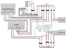
For those of you trying to follow along, here is the Growatt System Diagram from the manual:

Screen Shot 2024-01-06 at 5.55.26 PM.png
 
Last edited:
I'm really liking that Victron over the Growatt. They have better features and hardware IMO and documentation as well. Even though it costs more I'm ready to pull the trigger as it looks like it will work with my setup.

It is 32A and the Growatt only puts out 25A on backup so I don't need anything bigger. But should I look to replace the breaker with a 25 amp?

Also there is a relay inside that bonds N to G, but mostly out of curiosity, where does it get the signal from? It just shows a mysterious connection to the inverter. Not a issue in my situation thigh because I would disable that feature anyway since it will be feeding into my main panel which already has N-G bonded.

Does your inverter put out 25A at 240V? If so, it could support 50A at 120V. But the autotransformer is only good for 28A continuous, 32A intermittent, on neutral.

The setup is nice in that lets a larger inverter supply heavier 240V loads, and transformer is protected.

No point in putting a 25A breaker on a 25A inverter. It can't be counted on to trip it. But, it might nuisance trip above 20A load.
32A breaker is a suitable disconnect for your application, and it will get tripped by the adjacent shunt-trip device if thermostat indicates over-temperature.

Auto-transformer in parallel with the grid is a separate issue. I looked at the schematic and thought I might modify it to do dynamic bonding of center tap to neutral if I used it.

And then there is the imbalance between windings. Only 1V someone said? I thought it was 3V or 6V. The transformer began life as an isolation transformer for 220V. On the bright side, applying 120V to a 220V winding (or 240V to two windings in series) does mean lower no-load current so your inverter doesn't have to work hard doing nothing.
 
I just looked at the manuals for the Growatt MIN 11400TL-XH-US and the ATS 11400T-US Autotransformer.
They seem well matched (intentionally), I don't understand the EPS part of it, but there are no schematics for the ATS.
I don't think moving to the Victron autotransformer is useful for that configuration.
Edit: OK, the "EPS" switch between grid and inverter happens in the Autotransformer. That's different, Victron's does not do that.

If you've moved down to the 5k, maybe that makes sense as Victron AT gets you some more amperage.
Also, the ATS-US is UL1741. Victron only has CE/IEC certifications (as usual).

For those of you trying to follow along, here is the Growatt System Diagram from the manual:

View attachment 187317
I don’t think UL1741 would be relevant for the ATS

There is no inverting going on in there. And you can install the ESS/grid tie features without it.

And then there is the imbalance between windings. Only 1V someone said? I thought it was 3V or 6V.
I was guessing. I can believe 3V or 6V in isolation, but I can’t believe they can sell a UL listed product if it stays even 1V if connected to utility transformer like their wiring diagram allows
 
I don’t think UL1741 would be relevant for the ATS
Me either, but that's what SS lists on their website for UL Certifications.

The Certificate document (Intertek) actually says:
Inverters, Converters, Controllers and Interconnection System Equipment for use with Distributed Energy Standard(s): Resources [UL 1741:2010 Ed.2+R:16Sep2020]

So I guess an autotransformer is considered to be "Interconnection System Equipment". Learned something new.

 
And then there is the imbalance between windings. Only 1V someone said? I thought it was 3V or 6V.
OK, just did a real-world test with the 100A Victron autotransformer.
Both L1 and L2 are drawing about 8A on my critical loads panels.
Hopefully no one starts a load of laundry.

On grid (no autotransformer): L1 123V, L2 120V (imbalance in house wiring and out to POCO transformer).
Inverting on autotransformer: L1 116V, L2 119V (imbalance in autotransformer windings and house wiring).
Looks like a 6V swing to me.

Am I happy about 116V? No, but everything works fine.
Yes, I could adjust the output voltage on my Quattros (differently for each leg) to make up for the difference.
Maybe I'll do that to get a nice even 120V with a moderate load.
 
Last edited:
OK, just did a real-world test with the 100A Victron autotransformer.
Both L1 and L2 are drawing about 8A on my critical loads panels.
Hopefully no one starts a load of laundry.

On grid (no autotransformer): L1 123V, L2 120V (imbalance in house wiring and out to POCO transformer).
Inverting on autotransformer: L1 116V, L2 119V (imbalance in autotransformer windings and house wiring).
Looks like a 6V swing to me.

Am I happy about 116V? No, but everything works fine.
Yes, I could adjust the output voltage on my Quattros (differently for each leg) to make up for the difference.
Maybe I'll do that to get a nice even 120V with a moderate load.

Is the L1,L2, and neutral all connected to grid (including with indirect paths)?
 
Is the L1,L2, and neutral all connected to grid (including with indirect paths)?
Ground is ground everywhere, bonded to grid Neutral at the main service panel.
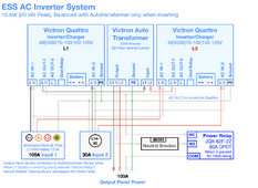
A power relay is used to switch Neutral between on-grid and inverting modes.

When on grid:
Critical load panel's L1 and L2 are connected to autotransformer L1 and L2 outputs.
Autotransformer Neutral is not connected to anything (AT still appears to draw about 30VA, uncertain on actual wattage)
Critical load panel Neutral is connected to grid neutral through the power relay.
Autotransformer L1 and L2 inputs are connected to grid through 2x Quattros. The grid passthrough relays in the Quattros are active.
Quattro Neutrals are connected together and to the grid Neutral.

When inverting:
Critical load panel's L1 and L2 are connected to autotransformer L1 and L2 outputs (same as on-grid).
Autotransformer Neutral is connected to the critical load panel (which also connects it to grid Neutral).
Critical load panel Neutral is connected to grid Neutral (same as on grid, but no current will flow to grid because L1 and L2 are not connected)
Autotransformer L1 and L2 inputs are connected to 2x Quattros output (pv/battery power and inverting)
Quattro Neutrals are connected together only (current only flows between Quattros, which balances them making them a 240V source)

Here are block diagrams:

ESS AC Wiring.png AT Balancing.png
 
Last edited:
Ok, when inverting is the grid AC in disabled? That would mean the AT cannot form a circuit with the grid transformer. In that case the voltage imbalance between legs shouldn’t be of concern. 6V is well within allowed U.S. grid voltage variance anyway.

I guess for some edge cases like brewing or roasting coffee without a PID control you’ll get confused if you plug into the wrong leg and get 10% different heat /s
 
That would mean the AT cannot form a circuit with the grid transformer. In that case the voltage imbalance between legs shouldn’t be of concern. 6V is well within allowed U.S. grid voltage variance anyway.
Yes, that was the intent, and it took me a while to figure out how to do that, while still keeping the house neutrals and grounds in the walls as is.
I was really paranoid about having a floating neutral situation. And about having objectionable current on ground lines.

Agree on the variance being allowed, but since @Hedges keeps pointing out the imbalance, I'll boost the Quattros voltage so I get to 120V on both legs.
Engineers are frequently perfectionists for things that probably don't matter. :)

I guess for some edge cases like brewing or roasting coffee without a PID control you’ll get confused if you plug into the wrong leg and get 10% different heat /s
My 12 cup Cuisinart grinder/brewer gets extensive use when the power is out for long periods!
It's one of the perks (pun intended) of having all of this equipment. :p
 
What was your risk/benefit analysis on your control line fusing (the 1A ones?) When I saw them I thought maybe they would magnify the matrix of partial fault cases that need to be considered, but after looking at it for 10 min I couldn't see something that was obviously bad.

My 12 cup Cuisinart grinder/brewer gets extensive use when the power is out for long periods!
It's one of the perks (pun intended) of having all of this equipment. :p
Haha. While I do have a keen palate for good coffee... I'm also super lazy so I keep a lot of instant coffee around.

How much surge does that draw?
 
What was your risk/benefit analysis on your control line fusing (the 1A ones?) When I saw them I thought maybe they would magnify the matrix of partial fault cases that need to be considered, but after looking at it for 10 min I couldn't see something that was obviously bad.
Cardinal rule: When one of these fuses blow or the breaker trips, it must fail SAFE, which in this case disables the autotransformer and returns Neutral to normal connection.

Honestly, I'm pretty sure I started with 1A fuses, and cut them down to like 0.1A. The power relay coil does not need 27W, it was like 500 mW if I recall. Each fuse is just good engineering practice, and probably overkill. What if the cheap potted 24V to 12V buck shorts out? That's the first one. What if the second pole of the Neutral breaker (12 VDC) gets shorted to AC power? That's the second fuse. I have no explanation for the third fuse except I was getting carried away. I guess if the power relay coil shorted out, or the flyback diode shorted.

How much surge does that draw?
Haven't measured it. I did have one burn up on me once, and had to pick it up and throw it outside while it was smoking.
I'm more concerned with well pumps, septic pumps, and refrigerators, whose surge is an order of magnitude larger.
 
Last edited:
Cardinal rule: When one of these fuses blow or the breaker trips, it must fail SAFE, which in this case disables the autotransformer and returns Neutral to normal connection.
OK so in this case it goes to the inverter stack's neutral instead of the AT's neutral, so there is never a floating neutral?
 
Back
Top