diy solar

diy solar

Use Main Panel as Critical Loads Panel?

I'm really liking that Victron over the Growatt. They have better features and hardware IMO and documentation as well. Even though it costs more I'm ready to pull the trigger as it looks like it will work with my setup.

It is 32A and the Growatt only puts out 25A on backup so I don't need anything bigger. But should I look to replace the breaker with a 25 amp?

Also there is a relay inside that bonds N to G, but mostly out of curiosity, where does it get the signal from? It just shows a mysterious connection to the inverter. Not a issue in my situation thigh because I would disable that feature anyway since it will be feeding into my main panel which already has N-G bonded.
 
Note that the coil is identical to the 32A version, same neutral current limitation.
That is impressive that the same coil can supply a load 3 times larger. Makes me feel even better running a measly 25 amps through it. But what is the neutral current limitation? Do you mean unbalanced phases?
 
Getting back to the AC disconnect, does anyone see why I should use a 3 pole fused switch as suggested by the U of Maryland video? I found one 20 miles away for a decent price, but it is physically larger than a 2 pole.

Other than that, I'm ready to order all the other miscellaneous components, unless you see something amiss in my sketch.

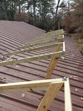
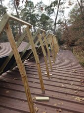
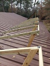
Oh, and if you're interested, you can see I'm making progress elsewhere. Here are a few pics of the tiltable panels on my barn. This is the first group of three.20240103_142121.jpg20240103_160945.jpg20240104_103543.jpg
 

Attachments

  • 20240103_142121.jpg
    20240103_142121.jpg
    270 KB · Views: 1
) time stamp around 3:35 and maybe elsewhere that if the inverter is transformrerless, you may want to switch the neutral so you can fuse the neutral. Does that make sense?


One additional question. The 400 amp disconnect at the meter currently supplies 3 panels. One near the meter (100 amp) one at the house (200 amp) where the taps are, and one at the barn (200 amp) 75 feet away from the house. This totals 500 amps, but is it like the breakers in a panel, where the total of the individual breakers can exceed the main rating, since all loads are not on at the same time?
Yes you can exceed as long as load calcs pass & the special solar backfeed calcs pass.
time stamp around 3:35 and maybe elsewhere that if the inverter is transformrerless, you may want to switch the neutral so you can fuse the neutral. Does that make sense?
I don't see the reference in the video. Vast majority of string inverters are transformerless. Microinverters are more likely to be transformer isolated. Fusing neutral has risk of killing equipment on 120/240V if neutral breaks before the hot legs (Google lost neutral, same risks as if POCO loses neutral). I don't see why transformer vs transformerless makes a difference for switching/fusing the neutral.

Just to clarify, the auto transformer will only try to balance if the backup output of the inverter is on when connected to the grid (not in battery backup mode)? Let's say it is on, which I'm not sure why it would be, how does that affect the autotransformer downstream? I don't see how there is a completed circuit since the only possible connection is through Neutral with no return path. This all may be moot since I planned to use a 3 pole manual transfer switch. So unless I forget to switch it to 'off', is that the only way it can try to balance? And if I did forget, is it dangerous or could it damage the transformer? If the answer to that last question is yes, how about adding a relay so that it can't connect unless the grid is off?

The backup output of the inverter might be on for common use cases of the inverter, EG to power critical loads at all times. (I don't know how the 240V Growatt is intended to be used. 120V and 120/240V inverters I believe often work this way).

If it is on then there are several situations where there will be a circuit through the inverter to grid. For instance, if the inverter is in bypass mode or inverter is on and parallel to grid (which is the case when exporting). It's a grid tie inverter so the chances are rather high.

EDIT: Timselectric did something similar as described in post #1 of this thread: https://diysolarforum.com/threads/growatt-spf-5000-es-at-and-n-g-solutions.36370/
To solve all of these issues, this is what I have done.

1) I ran a neutral conductor from the main panel to the loads panel. (Not bonded at the loads panel)
This provides a neutral for the loads in bypass mode. And provides the N/G bond from the main panel, in all modes.

2) install a relay on the AT feed conductors. Which is controlled by the inverter grounding relay. To only turn on the AT in battery mode.

EDIT 2 Actually, is this even an issue since my main breaker is interlocked with the generator/inverter circuit breaker and therefore the autotransormer can never be connected to the grid.
I think I've seen this before from timselectric and circled back to it earlier in the thread.
 
Yes you can exceed as long as load calcs pass & the special solar backfeed calcs pass.
I performed the load calcs and they were good, but since I'm not backfeeding through the main panel, do I need to do any other calculations?
 
Oh, makes sense. Question- I've seen that term here quite a bit, but what does bypass mean?
I don't know if it's an official term. For these autotransformers it refers to the fact that 240V (and balanced 120V) loads can be powered without the involvement of the autotransformer, the current for those loads just goes around the AT coils.

So the Victron comes in (I think) 32A and 100A bypass versions which is the maximum 240V / balanced 120V load that can go through without tripping. And the wires & whatnot will be sized appropriately to support that too.
I performed the load calcs and they were good, but since I'm not backfeeding through the main panel, do I need to do any other calculations?
For a grid tie inverter, you have to do the load side connections calculations for all feeders and busbars, all the way out to your service entry.
 
The backup output of the inverter might be on for common use cases of the inverter, EG to power critical loads at all times.
Doh! I should have known that. Well even if it is on all the time, I should be okay since the generator/inverter breaker is interlocked with the main and the only thing left in circuit is neutral.
 
Doh! I should have known that. Well even if it is on all the time, I should be okay since the generator/inverter breaker is interlocked with the main and the only thing left in circuit is neutral.

You're not interlocking the inputs to the AT IIRC. Suppose the Growatt is connected to grid and inverter is exporting. This means that the emergency power output will also be connected to the one AC system (there is no isolation). So that means your AT is also connected to grid / utility transformer L1/L2. The center tap of the AC goes eventually back to the utility transformer neutral.

BTW it's possible timselectric's circuit (adding a new neutral relay and tying it to N-G forming relay) can increase risk of equipment damage, if the new neutral relay is stuck but you've sent L1/L2 to your loads. If the N-G forming relay breaks, most loads are OK, you just have a safety risk and some equipment that requires N-G to be present will stop working.
 
For a grid tie inverter, you have to do the load side connections calculations for all feeders and busbars, all the way out to your service entry.
Just when I think i've covered everything, wham! I get schooled again:). Sorry for being so uninformed; I thought I did my homework.

Anyway, since my inverter will be tapped at the junction box directly to the 400 amp service and the inverter can only output 48 amps to the grid, what kind of calculation do I need to do?
 
You're not interlocking the inputs to the AT IIRC. Suppose the Growatt is connected to grid and inverter is exporting. This means that the emergency power output will also be connected to the one AC system (there is no isolation). So that means your AT is also connected to grid / utility transformer L1/L2. The center tap of the AC goes eventually back to the utility transformer neutral
Ah yes, forgot about that too. So its late, please tell me again why this is bad. If it is real bad, couldn't I put in another relay there, or manual cutoff, between the inverter and autotransformer cutting off all three legs. I think that is different than what Timselectric did.
 
Just when I think i've covered everything, wham! I get schooled again:). Sorry for being so uninformed; I thought I did my homework.

Anyway, since my inverter will be tapped at the junction box directly to the 400 amp service and the inverter can only output 48 amps to the grid, what kind of calculation do I need to do?
Do you know what the busbar limit is on that last thing with 500A of breakers in it?

I am not super familiar with how to handle those. Because you have no main breaker on it, and it adds up over 400A of attached breakers. It might need an EE stamp (I know there were some threads on Mike holt forum about simple rules to help you pass this but I think NEC rejected it, which means maybe you would need an EE to write up basically what those proposals would have let you directly pass by doing an additional allowed standard calculation method).
 
Last edited:
Ah yes, forgot about that too. So its late, please tell me again why this is bad. If it is real bad, couldn't I put in another relay there, or manual cutoff, between the inverter and autotransformer cutting off all three legs. I think that is different than what Timselectric did.

If the autotransformer neutral is at 1V relative to grid neutral due to imbalanced windings then there will be current flow to allow both voltages on the same wire. (It probably won’t be as high as 1V, I don’t know the circuit analysis. There are people on Victron forum complaining about this from time to time).

I’m not sure what the right fix is.
 
Do you know what the busbar limit is on that last thing with 500A of breakers in it?
I might have misunderstood. If you have 400A of fuses in the disconnect then I know how to calculate it.

If you have a 400A panel onto which you can plug three breakers, and you have a 200, 200, and 100, and they’re all on the same bus, then we need to dig into it more. At minimum need a wiring diagram from the equipment showing the layout
 
If the autotransformer neutral is at 1V relative to grid neutral due to imbalanced windings then there will be current flow to allow both voltages on the same wire. (It probably won’t be as high as 1V, I don’t know the circuit analysis. There are people on Victron forum complaining about this from time to time).

I’m not sure what the right fix is.
Got it, thanks. I'll look for their complaints, but do you recall if it is a safety issue/causing equipment damage, or is it just a nuisance? If more than a nuisance, then it is getting way too complicated and maybe I should give up on this.
 
Got it, thanks. I'll look for their complaints, but do you recall if it is a safety issue/causing equipment damage, or is it just a nuisance? If more than a nuisance, then it is getting way too complicated and maybe I should give up on this.
I have no idea. There are multiple opinions on this forum. Some people are clearly super triggered by it (here and at Victron forum). But manufacturers are willing to ship equipment that is (I think) code compliant to connect this way.

EDIT: it’s possible that the triggered people haven’t done the math. Maybe the much burlier utility transformer can beat the autotransformer into submission, resulting in pretty low balancing current contribution from the AT.

It will burn SOME electricity. It’s possible this tax is worth the simplification.
 
If you have a 400A panel onto which you can plug three breakers, and you have a 200, 200, and 100, and they’re all on the same bus, then we need to dig into it more. At minimum need a wiring
No, it is simpler than that, I think I can explain without a schematic. There is a 400 amp disconnect right after the meter. From that disconnect, there are 3 sub panels. One is 100 amps a foot away from the disconnect, one is 200 amps at the house 300 feet away and another 200 amps at the barn 75 feet from the house. The house panel is fed by 350MCM wire. From there it is tapped and 2/0 wire goes to the barn.
 
No, it is simpler than that, I think I can explain without a schematic. There is a 400 amp disconnect right after the meter. From that disconnect, there are 3 sub panels. One is 100 amps a foot away from the disconnect, one is 200 amps at the house 300 feet away and another 200 amps at the barn 75 feet from the house. The house panel is fed by 350MCM wire. From there it is tapped and 2/0 wire goes to the barn.
Do you mean 2x 400A fuses in that 400A disconnect. And then lugs/feeder wires out of that going to each panel?

If so then you do feeder calculation. Depending on what the relative position of grid and inverter is, the math is different. Basic idea is, is it possible for you to exceed the current on a particular segment of wire from the combined current from the grid and the inverter. If the grid and inverter are on the same side of a segment, then they can combine in a bad way (theoretically) that is worse than just the grid alone. So a OCPD or bigger wire may be needed once inverter is added, where it's not needed when only grid.
 
Do you mean 2x 400A fuses in that 400A disconnect. And then lugs/feeder wires out of that going to each panel?
Yes to both.
If so then you do feeder calculation. Depending on what the relative position of grid and inverter is, the math is different. Basic idea is, is it possible for you to exceed the current on a particular segment of wire from the combined current from the grid and the inverter. If the grid and inverter are on the same side of a segment, then they can combine in a bad way (theoretically) that is worse than just the grid alone. So a OCPD or bigger wire may be needed once inverter is added, where it's not needed when only grid.
The math seems trivial, even unnecessary. But then, my logic is surely flawed. If the inverter is feeding the grid, then the house is using less than what the inverter is putting out. Since that is much less than what the system can handle, there is no issue. And if the inverter is not feeding the grid, then either it is night, thus no issue, or the house is using both from the grid and the inverter. But the current from the inverter is going to the house and doesn't ever travel to the service lines. So as long as my tap to the inverter and main panel is sized correctly, thats all I should have to worry about. Please set me straight.
 
Back
Top