diy solar

diy solar

Muller Industries - BMS for Valence U27-12XP

Here is pics of the MULLER BMS. Anybody know how to hook it up in a 48V system? I have 5 banks of 4 12 Valence. Seth says it's programed for 48V. I circled the wire #'s that are on the pin outs.


You'll need one or two of these and they come in packs of 8.

What kind of inverter do you have? What kind of charge controller do you have?
 
Why do I need resistors?
Changing over to a MPP Solar LV5048 Split Phase Inventer which has 2 80 Amp MPPT chargers in it. Currently running a Outback 3524 with 2 FM80-150's. Array is 6 sets of 3 250 Watt panels on West roof and adding 6 sets of 3 160 Watt panels on East roof.
 
Why do I need resistors?
Changing over to a MPP Solar LV5048 Split Phase Inventer which has 2 80 Amp MPPT chargers in it. Currently running a Outback 3524 with 2 FM80-150's. Array is 6 sets of 3 250 Watt panels on West roof and adding 6 sets of 3 160 Watt panels on East roof.
I'm not sure how that inverter would handle without a resistor but you'll have a very large battery Bank so I'd recommend getting the resistor. Buy three of the ev200 contactors from eBay with, economizers make sure it has the economizer. Put the charge contactor between the panels and the inverter. if one of the cells goes over voltage the BMS will open the contactor and disconnect the solar panels. Set it to charge from the generator to a lower voltage then the panel so you don't have to worry about any cell over-voltage issues when you're running the generator.

Set the inverter to shut down at 50 volts. I'm assuming it's charger will continue to function even when the inverter shut down because the volts fell below 50.

use 2 contactors between the battery and the inverter. one of the contactors would be for the pre-charge resistor and the other would be for the main connection.

Otherwise the BMS is pretty self-explanatory. You've already highlighted the wires you need and the Mueller PDF file clearly states that the ones they highlighted in red and black are required for it to function. you'll probably want to put a little toggle switch on one of the little 12 volt wires to the BMs in order to power it on and off.

You should not take 12 volts from one of the valence batteries out of the string. Get a 48 volt to 12 volt Buck converter of 7 amps or more output. connected to the contactor for it's 48 volt Supply so that it's Supply gets shut off if the BMS decides to shut everything down. Hook up a momentary push button that connects the pre-charge resistor relay main studs together. This will be the button you push in order to turn everything on. You'll have to hold it down long enough for the BMS to boot up and when you hear the BMS click the pre-charge contactor you can release the button.

Your BMS connector that only has 4 wires coming out is for the contactors. If you want to get fancy you would add four more wires and then you'd have enough to power all 4 contactors but you'd only need at most three. Pros and cons are that contactors do use a few Watts. the precharge contactors aren't an issue because they're only on for 2 seconds and you won't need a precharge contactor between the panels and the inverter.
.

I haven't experimented yet with how the charge contactor functions compared to the main contactor but I'm hoping that you could use the pair to your benefit. like put the charge contactor between the panels and the inverter and put the main contactor between the inverter and the batteries. I would hope that in an over voltage situation the BMS would only open the charge contactor. Because if it left the main contactor connected the inverter would remain on and be able to bring the battery voltage down. this would take some actual Hands-On experimentation to decide if it functions the way we want it to because the manual is not clear enough.

the reason you may need to charge contactor to disconnect the panels is because most systems cannot be connected to panels when there's no battery connected. So hopefully that charge contactor will open anytime the main contactor opens. If not then you'll be forced to put the main contactor between the panels and the inverter. then you would have no contactor between the batteries and the inverter in this would be bad if the BMS had to shut everything down and couldn't. not really a problem if you trust your inverters low voltage cutoff and you said it high enough like 50 volts. Not really a problem if you're close by to monitor things and you'll realize when things get shut down. you'll probably want to hook a speaker to the alarm output of the BMS to get your attention. that's the last thing you want is the contactor to open and disconnect the panels without you knowing and while you're using up all the battery power. I really do have some experimenting left to do on this situation. there's lots of ways to go about it to make everything function properly even if the BMS doesn't do it naturally. We still have no confirmation that these bms's prevent charging while freezing.

Do you know if your hybrid inverter can handle being disconnected from the batteries while the solar panels are still connected?
 
You need resistors because your batteries are so dang powerful that if you connect the wires to the inverter without first going through the resistor all the capacitors in the inverter will charge instantaneously causing a very large spark when you connect the wires. The spark is large enough to explode wires, melt contactor terminals, and occasionally fry components inside the inverter itself. Don't ask me how I know.

These batteries can surge at 2000 amps. You have five strings. 5x2000a x 54v is 536,000watts. You've got massive bragging rights.
 
Changing over to a MPP Solar LV5048 Split Phase Inventer which has 2 80 Amp MPPT chargers in it.
People all around having good luck with those. if you don't need 240 though did you know you can combine both of the outputs into one single 120 volt output? It looks like on the LV 5048 it's line 28 change it between 2A0 and 2A2. And that theoretically changes its output between a matched 120 phase out put and 240 v

I've looked inside and it looks to me like you can completely disable one of the inverters saving half of the standby power for those times when you know that you're not going to need more than 2500 watts. to accomplish this it probably would have been easier to get a couple of their 3000 watt models but I noticed they're only available in the 24 volt right now.
 
You need resistors because your batteries are so dang powerful that if you connect the wires to the inverter without first going through the resistor all the capacitors in the inverter will charge instantaneously causing a very large spark when you connect the wires. The spark is large enough to explode wires, melt contactor terminals, and occasionally fry components inside the inverter itself. Don't ask me how I know.

These batteries can surge at 2000 amps. You have five strings. 5x2000a x 54v is 536,000watts. You've got massive bragging rights.
I picked up the one Will Prowes suggested when he did his evaluation of that Inverter setup.
 
I'm not sure how that inverter would handle without a resistor but you'll have a very large battery Bank so I'd recommend getting the resistor. Buy three of the ev200 contactors from eBay with, economizers make sure it has the economizer. Put the charge contactor between the panels and the inverter. if one of the cells goes over voltage the BMS will open the contactor and disconnect the solar panels. Set it to charge from the generator to a lower voltage then the panel so you don't have to worry about any cell over-voltage issues when you're running the generator.

Set the inverter to shut down at 50 volts. I'm assuming it's charger will continue to function even when the inverter shut down because the volts fell below 50.

use 2 contactors between the battery and the inverter. one of the contactors would be for the pre-charge resistor and the other would be for the main connection.

Otherwise the BMS is pretty self-explanatory. You've already highlighted the wires you need and the Mueller PDF file clearly states that the ones they highlighted in red and black are required for it to function. you'll probably want to put a little toggle switch on one of the little 12 volt wires to the BMs in order to power it on and off.

You should not take 12 volts from one of the valence batteries out of the string. Get a 48 volt to 12 volt Buck converter of 7 amps or more output. connected to the contactor for it's 48 volt Supply so that it's Supply gets shut off if the BMS decides to shut everything down. Hook up a momentary push button that connects the pre-charge resistor relay main studs together. This will be the button you push in order to turn everything on. You'll have to hold it down long enough for the BMS to boot up and when you hear the BMS click the pre-charge contactor you can release the button.

Your BMS connector that only has 4 wires coming out is for the contactors. If you want to get fancy you would add four more wires and then you'd have enough to power all 4 contactors but you'd only need at most three. Pros and cons are that contactors do use a few Watts. the precharge contactors aren't an issue because they're only on for 2 seconds and you won't need a precharge contactor between the panels and the inverter.
.

I haven't experimented yet with how the charge contactor functions compared to the main contactor but I'm hoping that you could use the pair to your benefit. like put the charge contactor between the panels and the inverter and put the main contactor between the inverter and the batteries. I would hope that in an over voltage situation the BMS would only open the charge contactor. Because if it left the main contactor connected the inverter would remain on and be able to bring the battery voltage down. this would take some actual Hands-On experimentation to decide if it functions the way we want it to because the manual is not clear enough.

the reason you may need to charge contactor to disconnect the panels is because most systems cannot be connected to panels when there's no battery connected. So hopefully that charge contactor will open anytime the main contactor opens. If not then you'll be forced to put the main contactor between the panels and the inverter. then you would have no contactor between the batteries and the inverter in this would be bad if the BMS had to shut everything down and couldn't. not really a problem if you trust your inverters low voltage cutoff and you said it high enough like 50 volts. Not really a problem if you're close by to monitor things and you'll realize when things get shut down. you'll probably want to hook a speaker to the alarm output of the BMS to get your attention. that's the last thing you want is the contactor to open and disconnect the panels without you knowing and while you're using up all the battery power. I really do have some experimenting left to do on this situation. there's lots of ways to go about it to make everything function properly even if the BMS doesn't do it naturally. We still have no confirmation that these bms's prevent charging while freezing.

Do you know if your hybrid inverter can handle being disconnected from the batteries while the solar panels are still connected?
Thanks for all the info. I need to print it out and go through it. I beleive I saw on YouTube someone running there without batteries as a test. I'll probably run it 110V but I have a few shop items that take 220V but over the years I've found it more economical to run big loads of the diesel gen set. I usually set the inverter to fire up the gen if it sees a certain amperage for a set time to save the batts. I talked to Ean (Great guy and he is a testament to customer support) and either he told me or I read in the literature it is basically 2) 2000 watt inverters in there. Maybe I can set a breaker or switch to disable one side as I noticed the watts overhead was a bit more than my old Trace 3624 and also the Outback 3524. So far on the Outback and the current 12 panels I don't have an issue with overcharging, wish I did. But once the rest go up it may become an issue. Solar at 24V is running 18kWh a day and the small house load runs 6-10 kWh.
 
Last edited:
I picked up the one Will Prowes suggested when he did his evaluation of that Inverter setup.
You need resistors because your batteries are so dang powerful that if you connect the wires to the inverter without first going through the resistor all the capacitors in the inverter will charge instantaneously causing a very large spark when you connect the wires. The spark is large enough to explode wires, melt contactor terminals, and occasionally fry components inside the inverter itself. Don't ask me how I know.

These batteries can surge at 2000 amps. You have five strings. 5x2000a x 54v is 536,000watts. You've got massive bragging rights.
I tested the batteries and they came up at about 100ah's from the rated 130 on the label. They are the Valence U27-12XP. You may know what its like to maintain lead acid of the last 40 years, not fun! Hopefully even though the Valence are used I'll get a long life. Trying to set to stay between 20% and 80% of capacity. I hear there happy in that range. So I'm figuring at 24V I have 1000a and when I go to 48V(54v) I'll have 500a or 27k watts. Did I figure that right?
 
I tested the batteries and they came up at about 100ah's from the rated 130 on the label. They are the Valence U27-12XP. You may know what its like to maintain lead acid of the last 40 years, not fun! Hopefully even though the Valence are used I'll get a long life. Trying to set to stay between 20% and 80% of capacity. I hear there happy in that range. So I'm figuring at 24V I have 1000a and when I go to 48V(54v) I'll have 500a or 27k watts. Did I figure that right?

Yes that's 500 amp hours. And around 27 kilowatt hours.
BUT...
I doubt they're only one hundred amp hours. I tested hundreds and always had over 96% capacity. Batteries with 700 cycles measured 96% and batteries with 200 cycles measured 98%. Batteries with less than 20 cycles measured 105% It's possible you're not accounting for inverter losses or maybe they weren't properly top balanced before the test.
 
You may know what its like to maintain lead acid of the last 40 years, not fun! Hopefully even though the Valence are used I'll get a long life.

QUOTE]
I definitely know what it's like dealing with lead acid. I've been through a few 40kwh sets. These lithium's have been an absolute lifesaver for me. Power in and power out is so efficient I'm ending up with a lot more power than I used to get. They don't get hot they don't smell bad they don't need water. They don't get corroded terminals. They don't need to be full every day. And if the sun peeks out at 10 a.m. they don't miss out on that precious burst of power by going into absorb mode so easily so they're actually capable of absorbing everything my panels have to give up until their 99.5% full before they finally hit absorbe. I have 220kwh of U27-12XP
but settled on setting up 65kwh on my house. Compared to my lead it feels like a rocket ship versus roller skates.
 
Try that with a 10-year old lead battery. Not a chance!
 
I tested the batteries and they came up at about 100ah's

I assume you've read the valence super thread? It goes into good detail on balancing.
 
I assume you've read the valence super thread? It goes into good detail on balancing.
Thanks! I'll explore that thread.
 
I assume you've read the valence super thread? It goes into good detail on balancing.
Thanks! I'll explore that thread.
Yes that's 500 amp hours. And around 27 kilowatt hours.
BUT...
I doubt they're only one hundred amp hours. I tested hundreds and always had over 96% capacity. Batteries with 700 cycles measured 96% and batteries with 200 cycles measured 98%. Batteries with less than 20 cycles measured 105% It's possible you're not accounting for inverter losses or maybe they weren't properly top balanced before the test.
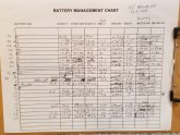
I used the Hall effect meter (https://www.amazon.com/dp/B07YWVCBRN/ref=cm_sw_r_sms_awdb_t1_xQQCEb97VTHSH) to check each battery. Also was able to monitor with the Valence software. Used a 12 V 400 watt inverter and a couple 200 watt light bulbs for the load. Would charge to 14 volt and see the internal balancer kick in then I'd do the load/capacity test down to 10% according to the Valence software. I I recorded Ah and Wh. Here's my scribble on that.
 

Attachments

  • 20200811_093430.jpg
    20200811_093430.jpg
    101.1 KB · Views: 15
Thanks! I'll explore that thread.

I used the Hall effect meter (https://www.amazon.com/dp/B07YWVCBRN/ref=cm_sw_r_sms_awdb_t1_xQQCEb97VTHSH) to check each battery. Also was able to monitor with the Valence software. Used a 12 V 400 watt inverter and a couple 200 watt light bulbs for the load. Would charge to 14 volt and see the internal balancer kick in then I'd do the load/capacity test down to 10% according to the Valence software. I I recorded Ah and Wh. Here's my scribble on that.


The valence internal state of charge meter is inaccurate & so is its amp meter on 20% of the batteries I've dealt with.

You should charge up to a higher voltage and make sure it's properly top balanced before you do the test. Read the super thread for notes on top balancing. During the discharge test continue until it Falls to around 11 volts paying mind that no cell goes critically under voltage. The best way to do this is to use the valence BMS and run the discharger through the contactor configured for 1s 1p. You probably realized already that after the voltage falls under 13 it begins to fall fast and certainly Under 12 volts it falls so fast it's very hard to make sure your present and watching the individual cell voltages so relying on the BMS to cut the contactor as a backup is much more safe. I have six of the wattmeters you used. There are also not very accurate below 3 amps but you were pulling much more than that so it should be accurate enough for your test. When I tested I did a c20 using Wills battery capacity tester so I was only discharging at 6.9amps compared to you were probably discharging around 28 amps. Your discharge rate of 4 times faster would definitely play a part in our different results. I'd like to do another set of tests at different discharge rates and chart the results. One good thing about solar is you'll be discharging these battries gently in real use. Maybe overnight around 16 hours for most people but in your case since you have a lot of batteries even slower than that. That's a pretty slow gentle discharge compared to the high drain they're capable of.
 
Has anyone gotten a link to the CAN bus software mentioned in the Muller BMS documentation? I've emailed them probably 30 times about this specifically and they either have flat out ignored my emails or sent me an excuse and no answer. I'm nearing my wits' end with Muller Industries, absolute worst customer experience I've ever had in my life.
 
Has anyone gotten a link to the CAN bus software mentioned in the Muller BMS documentation? I've emailed them probably 30 times about this specifically and they either have flat out ignored my emails or sent me an excuse and no answer. I'm nearing my wits' end with Muller Industries, absolute worst customer experience I've ever had in my life.
Do you have a muller BMS? Did they go out of business? I heard a rumor they went out of business.
 
Do you have a muller BMS? Did they go out of business? I heard a rumor they went out of business.

Yea I've had one of their BMS for a while and have been hounding them for further information, documentation, software, etc. Their list of excuses from the beginning for failing to deliver has been unreal. I've heard everything from "wife is having a baby" to "paint is drying on the BMS" to "our email server was down and we just found out."

I'm unaware of them going out of business. Their website is still up and I got another excuse reply over Thanksgiving week of "we're out of the office this week and will get back to you next week" and it has been crickets ever since. I've even called out Seth Muller on Facebook in a DIY electric vehicle group and no response from him or anyone else. It's like Muller Industries is a topic nobody wants to even touch.
 
Has anyone gotten a link to the CAN bus software mentioned in the Muller BMS documentation? I've emailed them probably 30 times about this specifically and they either have flat out ignored my emails or sent me an excuse and no answer. I'm nearing my wits' end with Muller Industries, absolute worst customer experience I've ever had in my life.
D974B371-64F6-4BE3-BE2E-E6255C96B76A.jpeg
933DB887-56B9-4113-826D-BA9B639DC0AD.jpeg7B4DC95C-266A-4BAE-A67B-515D76BBA496.jpeg
 
Back
Top