diy solar

diy solar

Multiple inverters to one shared AC input?

erik.calco

Solar Badger
Joined
Nov 3, 2019
Messages
1,170
Location
USA
As a follow-up to this great question about combining SCCs, can you combine inverter outputs into one live?

I'm buying one of these manual transfer switch panels. They both take in two lives (110V). The difference is 30A and 50A inputs. All my AC load outputs are 20A; so this panel will have nothing but 20A breakers in it for output. You can have up to 3 or 5 on each L circuit from the inverter. Don't worry about load... assume not all switches will be on gen at any given moment. This is not a load question.

The question is, if I am producing 2.4Kw via one inverter, and I want to add another, is there a way to combine them into one 50A live input to this subpanel in parallel without backfeeding each other? Or, do they have to have their own dedicated L input into the panel?

If you can combine in parallel, then the 50A is definitely the way to go. It may still be the way to go if you think you'll be adding an inverter producing over 3600 watts next.
 
Last edited:
You need to sync the phases. Some inverters, such as many MPP units, can be paralleled, so that the AC outputs can be combined. With most off-grid inverters, this is not the case. There are inverter combiner systems, but they are expensive, so you are better off buying a single, bigger inverter.

If you wish to scale a system, the 2424lv MPP is great. I have 2 paralleled right now creating 4.8kw, and it is split phase, so I can feed my house panel if I need to. Another solid option is the 5048lv MPP. It can be paralleled up to 3 units.
I'm starting with the 2424lv. The 5048 really is just 2 x 2424lv in parallel with two lives out. They are not combined. There is a warning somewhere in one of those manuals about not combining in parallel due to backfeeding concerns. It does handle 240V well with 180 degree phase angle.

There is a "hint" that it may be possible, but far from clear:

1573658503858.png

The problem is that parallel in this manual always implies using separate lives, referring only to the inverters working together cooperatively (e.g., for phase angle and battery). Please correct me if I'm wrong.

They do expect the parallel units to share a battery bank regardless of AC configuration, but lack flexibility in battery voltage (cannot combine 2424lv with 5048lv because 24v and 48v).
 
Last edited:
Oh! I know this one. So they have extra wires included with the parallel board kit. Current share cables go between the two units. They are not to parallel the outputs. They are different.

And you can parallel the ac output to increase load capacity, and you can use individual units for various phases. 2 units to make split phase. And yes,, the 5048lv is two 2424lv boards when I opened it up. I like the 2424lv more now, because its small and easy to move around. the 5048 is huge.

Maybe @MPP Solar USA - Ian Roux can chime in? Maybe I am missing eriks question. The parallel operation means they can share the battery and the ac output, but it needs to be configured for that. If you want multiple phases, they need to be wired and configured for that instead.
 
@Will Prowse check out those HD transfer panels I linked. Spend a day thinking about the possibilities. It took me a day before it clicked in with that "oh shit" moment realizing how much flexibility you have when the grid is down when you can only supply "critical loads" while still being able to maximize savings using solar when the grid is up. The ONLY missing piece of the utopian puzzle is how to eventually provide 5kw single phase input into one L1 with two 2424lv.

E.g., In the Winter, my heater fan is my #1 critical load. In the summer, it is my least critical circuit. Hard for a desert lizard to imagine. I lived in AZ once. Waiting for A/C repair in 120F+ heat wave is not fun there. Letting your pipes freeze in OH is not an option.
 
Last edited:
Victron has a range of inverters/chargers that can be joined in a similar way too. More current into a single phase setup or 3 phase is possible.
 
Hello Guys.
Let me try to simplify.

Both units when connecting inverters in parralel need to be on the same battery.
LV2424 - Current sharing cables are only connected to inverters working on the same phase. (any parallel hookup requires signal cables - 15pin DB connector)
LV5048 - adding more inverters on same phase also require current sharing cables between them (any parallel hookup requires signal cables - 15pin DB connector)
Current sharing cables are NOT to be connected to inverters on different phases

LV5048 >> Hybrid LV2424 - -
Supports split phase out of the box setting 28=2A2 , 2.5kw per phase >> Need 2 or more for split phase operation (2 x 4.8kW or 2.4kw per phase)
Supports 5KW single phase (L1 and L2 tied , setting 28 = 2A0) >> two or more in parralel on the same phase , Inv 1 L1 and Inv 2 L1 tied
Parallel boards included inside inverter >> Bought separately


you can configure all inverters to be on the same 120V phase. the LV5048 can support up to 15Kw (3 in parallel), the Hybrid LV2424 can go up to 9 in parallel (21kW)

One major difference, is that I would be really nervous having such a large system running on a 24V system.
As an example
10 kW output on 48V (50V) is 10000/50=200A, on the same 24V system, you are talking 400A the differnce in battery cable size is huge. Also power loss is equal to the square of the current x resistance.

So for example, if your battery cables are lets say .0001 Ohm, 200 x 200 x .0001 = 4W loss whereas at 24V on 400A, that same cable will lose 400 x 400 x .0001 = 16W (heat),
that does not sound like much, but if your cables were .001 Ohm, your losses would be 40W and 160W respectively.

for smaller systems, this loss is negligible

Thats why they higher the battery voltage you can go to initially , the easier it is to grow your system, as the larger inverters generally run on higher battery voltages.

I use this volt drop calculator when estimating these losses for my solar, battery and AC cabling.


We are bringing out a 30KW inverter in the coming days, its battery voltage is 348 to 384VDC, and can handle 45Kw of solar, , with a solar voltage of between 450 to 900V DC. for about $9K (will be able to use an entire Nissan Leaf or Tesla Battery 375V)
The battery current at 30Kw output is only 30000/375 = 80A amps from the battery
 
Last edited:
Hello Guys.
Let me try to simplify.

Both units when connecting inverters in parralel need to be on the same battery.
LV2424 - Current sharing cables are only connected to inverters working on the same phase. (any parallel hookup requires signal cables - 15pin DB connector)
LV5048 - adding more inverters on same phase also require current sharing cables between them (any parallel hookup requires signal cables - 15pin DB connector)
Current sharing cables are NOT to be connected to inverters on different phases

LV5048 >> Hybrid LV2424 - -
Supports split phase out of the box setting 28=2A2 , 2.5kw per phase >> Need 2 or more for split phase operation (2 x 4.8kW or 2.4kw per phase)
Supports 5KW single phase (L1 and L2 tied , setting 28 = 2A0) >> two or more in parralel on the same phase , Inv 1 L1 and Inv 2 L1 tied
Parallel boards included inside inverter >> Bought separately


you can configure all inverters to be on the same 120V phase. the LV5048 can support up to 15Kw (3 in parallel), the Hybrid LV2424 can go up to 9 in parallel (21kW)

One major difference, is that I would be really nervous having such a large system running on a 24V system.
As an example
10 kW output on 48V (50V) is 10000/50=200A, on the same 24V system, you are talking 400A the differnce in battery cable size is huge. Also power loss is equal to the square of the current x resistance.

So for example, if your battery cables are lets say .0001 Ohm, 200 x 200 x .0001 = 4W loss whereas at 24V on 400A, that same cable will lose 400 x 400 x .0001 = 16W (heat),
that does not sound like much, but if your cables were .001 Ohm, your losses would be 40W and 160W respectively.

for smaller systems, this loss is negligible

Thats why they higher the battery voltage you can go to initially , the easier it is to grow your system, as the larger inverters generally run on higher battery voltages.

I use this volt drop calculator when estimating these losses for my solar, battery and AC cabling.


We are bringing out a 30KW inverter in the coming days, its battery voltage is 348 to 384VDC, and can handle 45Kw of solar, , with a solar voltage of between 450 to 900V DC. for about $9K (will be able to use an entire Nissan Leaf or Tesla Battery 375V)
The battery current at 30Kw output is only 30000/375 = 80A amps from the battery

Excellent info, @MPP Solar USA - Ian Roux . You answered my question. We can wire two 2424lv in parallel on one 120V phase with signal cables (the "parallel kit").

For 2 x LV2424, do you think I should go heavier than 4/0 with 24V? As I understand it, 2 x LV2424 @ 24V is 208amps.
 
Last edited:
Excellent info, @MPP Solar USA - Ian Roux . You answered my question. We can wire two 2424lv in parallel on one 120V phase with signal cables (the "parallel kit").

For 2 x LV2424, do you think I should go heavier than 4/0 with 24V? As I understand it, 2 x LV2424 @ 24V is 208amps.
If there is cable and terminal space available, I would double up with the 4/0, its easier to work with two smaller cables than one fat one that wont bend.

The cable I have been using is that is easy to work with is. Been using it for years, and then of course, good quality Lugs, with a good crimping tool

Most hot spots happen at a badly crimped lugs., And then add a bit of grease , and/or a bit of heatshink over the crimp to keep the battery acid and air out.

Ian
 
Excellent info, @MPP Solar USA - Ian Roux . You answered my question. We can wire two 2424lv in parallel on one 120V phase with signal cables (the "parallel kit").

For 2 x LV2424, do you think I should go heavier than 4/0 with 24V? As I understand it, 2 x LV2424 @ 24V is 208amps.
Another note, when you are connecting those two LV2424s in parallel, if you are just doing it single phase, 120V, then single phase AC input will be fine for both.
However, if you are connecting them up in Split phase, note that the only time you will get 240V split phase out, is when the inverters are running off a fully charged battery, the moment they switch over to Utility Charging, you will lose 240V (if your AC input is only Single Phase), but will still have 120V output on both L1s, but will be 120V to Neutral, and 0V between L1 and L2.
I have been spending hours at night trying to find a workaround for this, so far no luck on keeping the 240V going.
 
If there is cable and terminal space available, I would double up with the 4/0, its easier to work with two smaller cables than one fat one that wont bend.

By double up, you mean use 2 x 2/0 instead of 1 x 4/0?

The current plan is just 4/0 for the battery bank. The inverter would connect with 2/0. Is 2/0 overkill for one LV2424? Your link is for 4 gauge.

Also, considering welder's cable, which I understand is supposed to be more flexible. Looking to order from TEMCO and let them put on the lugs.
 
If there is cable and terminal space available, I would double up with the 4/0, its easier to work with two smaller cables than one fat one that wont bend.

Ian

I went with 4/0 for the bank (6" and 9" cables for 2S2P). But for the inverter side, I doubled up with 9' of 2 * 6 AWG per your and the LV2424 manuals recommendation, particularly since I'm not sure how that will run, yet.
 
Another note, when you are connecting those two LV2424s in parallel, if you are just doing it single phase, 120V, then single phase AC input will be fine for both.
However, if you are connecting them up in Split phase, note that the only time you will get 240V split phase out, is when the inverters are running off a fully charged battery, the moment they switch over to Utility Charging, you will lose 240V (if your AC input is only Single Phase), but will still have 120V output on both L1s, but will be 120V to Neutral, and 0V between L1 and L2.
I have been spending hours at night trying to find a workaround for this, so far no luck on keeping the 240V going.
One would think that if you feed utility with split phase, it would switch to split phase.
In other words, are you feeding the units off the same phase, or opposite phases?
 
One would think that if you feed utility with split phase, it would switch to split phase.
In other words, are you feeding the units off the same phase, or opposite phases?
An LV2424 unit by itself operates in single phase with one live, 20A at 120V. The manual documents how to do split phase where L1 and L2 would be 180 degrees. With LV2424, each unit adds a single live, so you can do split phase with 2 units by connecting them with the kit and configuring it for 180 degree phase angle. The LV5048 is basically two LV2424 units combined with the parallel kit internal, with an L1 and L2; but also uses a 48V battery bank instead of 24V.

So, what I was asking him is if I could combine the L1 and L2 with the same phase so I would have a single 40A 120V feed from two 20A 120V lives (L1 + L2). Basically, he said that yes, that is an option, but you still need the parallel kit for 2 * LV2424 which allows the units to work together and sync the phase. So whether you configure for 0 or 180 degrees, the units need to communicate and work together.

None of this is feeding the grid. It is acting as a generator in this topology. However, it does need to sync with the utility phase if it is combining utility input with gen (battery/PV) input to handle loads. But, that is not the type of sync'ing we were discussing. We were talking about it producing a single wave from two inverters independent of utility.

You do raise in interesting question, though. If you are bringing in split phase, but outputting only single phase, would it only use half of your AC input to help handle loads?
 
Last edited:
One would think that if you feed utility with split phase, it would switch to split phase.
In other words, are you feeding the units off the same phase, or opposite phases?
If you are feeding in split phase from the grid and your inverter is configured for split phase , you will have no problems.

I am trying to find a way to feed in single phase 120V (like from a generator), which charges the batteries at the same time, whilst the inverter outputs split phase. 120V-0-120V. Thats the trick (doing it all at the same time). But the inverters have safeties built into them that does not allow this operation. It will charge the battery from the generator, and output 120V single phase from both inverters, and when its done charging, switch entirely over to solar and battery, and will output split phase once again.
 
You need to sync the phases. Some inverters, such as many MPP units, can be paralleled, so that the AC outputs can be combined. With most off-grid inverters, this is not the case. There are inverter combiner systems, but they are expensive, so you are better off buying a single, bigger inverter.

If you wish to scale a system, the 2424lv MPP is great. I have 2 paralleled right now creating 4.8kw, and it is split phase, so I can feed my house panel if I need to. Another solid option is the 5048lv MPP. It can be paralleled up to 3 units.
This is pretty old but I'm really interested in the combiner system to put inverters in parallel. I got the wrong inverter and can't return anymore. I need to expand my system so I need to combine 2 inverters phases. Could you please provide few examples of systems that does that? Thanks
 
If you are feeding in split phase from the grid and your inverter is configured for split phase , you will have no problems.

I am trying to find a way to feed in single phase 120V (like from a generator), which charges the batteries at the same time, whilst the inverter outputs split phase. 120V-0-120V. Thats the trick (doing it all at the same time). But the inverters have safeties built into them that does not allow this operation. It will charge the battery from the generator, and output 120V single phase from both inverters, and when its done charging, switch entirely over to solar and battery, and will output split phase once again.
The trick is, and this is what i did, I wired a rectifier right off the AC on my little 1000 watt penny. That rectifier puts out.. 230 volts or something straight off the generator engine, and I feed that into the solar / MPPT side. The MPPT sees that as solar panels and does its only reconfig of the voltage to charge the battery. This gets around the need for multiple phases coming in and in theory would not cause a problem for the split phase configuration


This is what i got and it works great for charging batteries if there is no solar. I manually disconnect solar when i do this.

Three Phase Diode Bridge Rectifier​


Actually even better, if you have 2 inverters anyways, leave one with solar and dedicate the second solar input to the generator, that way no need to unplug either. The MPPT in each should manage it all.
 
Last edited:
I just really wish the 1012lv was parallelable. It seems nobody makes an AIO over 1Kw for 12v systems, but sometimes you just need a little more oomph!
 
The trick is, and this is what i did, I wired a rectifier right off the AC on my little 1000 watt penny. That rectifier puts out.. 230 volts or something straight off the generator engine, and I feed that into the solar / MPPT side. The MPPT sees that as solar panels and does its only reconfig of the voltage to charge the battery. This gets around the need for multiple phases coming in and in theory would not cause a problem for the split phase configuration

I have fed rectified AC to MPPT and had it work, so i agree with this. I have not fed multiple 'out of phase' AC sources to a 3 phase bridge rectifier but i do believe it would work, but might have efficiency issues. The real 'problem' i see, at least mentally, with JUST rectifying the AC is that without a large capacitor bank between the rectifier diodes and the MPPT, how much power the MPPT will able to make use of might really depend on whether your multiple AC sources are in phase or out of phase. I dont know if MPPTs can track the max power point at 50-60hz. Based on how slowly they load up solar circuits (over the course of multiple seconds, from what ive seen) i seriously seriously doubt it. But then you get into "that's a whole lot of 450v capacitors to fix this...". So far i have only used existing rectifier sections scavenged from other electronics which included capacitors appropriate for the power level of that device (i assume!) and paralleled those to hit a target throughput. I have not done math or added capacitance on my own.
 
I have fed rectified AC to MPPT and had it work, so i agree with this. I have not fed multiple 'out of phase' AC sources to a 3 phase bridge rectifier but i do believe it would work, but might have efficiency issues. The real 'problem' i see, at least mentally, with JUST rectifying the AC is that without a large capacitor bank between the rectifier diodes and the MPPT, how much power the MPPT will able to make use of might really depend on whether your multiple AC sources are in phase or out of phase. I dont know if MPPTs can track the max power point at 50-60hz. Based on how slowly they load up solar circuits (over the course of multiple seconds, from what ive seen) i seriously seriously doubt it. But then you get into "that's a whole lot of 450v capacitors to fix this...". So far i have only used existing rectifier sections scavenged from other electronics which included capacitors appropriate for the power level of that device (i assume!) and paralleled those to hit a target throughput. I have not done math or added capacitance on my own.
Good questions. I've had good luck. I've had my 1000 watt genny plugged into my 3kw eg4 units solar input and it was charging the batteries at 993 watts or so - it worked very well actually. I saw no issues. Its converting it to DC so is frequency a problem at that point? I don't think so, as the 3 phases are warped into one dc stream into the mppt and the inverter just sees fluctuating solar panels at that point producing about 1000 watts +- . As long as it looks like fluctuating solar and its within the voltage and current spec, I would think it should work fine.
 
Its converting it to DC so is frequency a problem at that point?
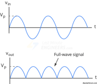
Good question. If you ONLY use diodes in a bridge rectifier configuration you are basically just flipping the waves from the bottom half of an AC waveform, back over onto the top half. It is still a 'wavy waveform' of DC, and if you started with 60hz you now have 120hz.
1694109369919.png

Then the question becomes, does the MPPT care about the voltage difference between the top of the waveform and the bottom of it? As far as i know an MPPT is just a switch mode power supply with a specialized control scheme, and SMPS in general supposedly "operate in the frequency range from about 10 kHz up to the MHz range.". So the hardware can certainly keep up with a 120hz waveform on the input, but i dont know at what 'speed' the control algorithm functions. Maybe it is fast enough that it sees the rapid fluctuations as actual varying solar power and is constantly restarting a 'tracking sweep' 120 times a second, never finding the max power point, and operating at reduced efficiency (but how much reduced?). Or, maybe it doesn't check the input for changes quite that often and it behaves as if it had a steady voltage source. I just dont know enough about how the control algorithm works to know. But in my mind there MAY be a situation where the MPPT is seeing the rapidly varying input voltage, and adding enough capacitance to smooth it out would actually let the MPPT operate more efficiently.

AKA a "capacitor input filter".

But, if it isn't a durability issue to feed the MPPT 120hz wavy DC, then it's probably not worth it to 'smooth out' the supply with capacitance, if i had to guess. And that's the thing, im a layman just guessing on EE topics. lol
 
Last edited:
Good question. If you ONLY use diodes in a bridge rectifier configuration you are basically just flipping the waves from the bottom half of an AC waveform, back over onto the top half. It is still a 'wavy waveform' of DC, and if you started with 60hz you now have 120hz.
View attachment 166434

Then the question becomes, does the MPPT care about the voltage difference between the top of the waveform and the bottom of it? As far as i know an MPPT is just a switch mode power supply with a specialized control scheme, and SMPS in general supposedly "operate in the frequency range from about 10 kHz up to the MHz range.". So the hardware can certainly keep up with a 120hz waveform on the input, but i dont know at what 'speed' the control algorithm functions. Maybe it is fast enough that it sees the rapid fluctuations as actual varying solar power and is constantly restarting a 'tracking sweep' 120 times a second, never finding the max power point, and operating at reduced efficiency (but how much reduced?). Or, maybe it doesn't check the input for changes quite that often and it behaves as if it had a steady voltage source. I just dont know enough about how the control algorithm works to know. But in my mind there MAY be a situation where the MPPT is seeing the rapidly varying input voltage and adding enough capacitance to smooth it out would actually led the MPPT operate more efficiently.

But, if it isn't a durability issue to feed the MPPT 120hz wavy DC, then it's probably not worth it to 'smooth out' the supply with capacitance, if i had to guess. And that's the thing, im a layman just guessing on EE topics. lol
Interesting... Ya I don't know myself otherwise. All i can say is that it was charging my batteries :) Hopefully it doesn't 'wear out' something. Didn't seem to cause any issues though and the volt meter was happy with the output too. Your mileage may vary, don't do what i do and all that. HAHA.. thanks!

EDIT: I should mention this is only used in an emergency situation, not a common usage thing.
 
I dont have a lot of actual hours doing it either, but only because i never tidied up my scavenged rectifier boards into a nice safe housing with no exposed high voltage!! It's on 'the list'. :ROFLMAO:
 

diy solar

diy solar
Back
Top