diy solar

diy solar

Multiplus II and Generator Connections

caymaanedge

New Member
Joined
Jul 19, 2020
Messages
124
My Multiplus II is blocking out one leg of my Onan generator. I am getting only 30amps of output through the inverter and occasionally I tri0 the Generator 30am0 breaker. I have read a fair amount but do not know that path to take to rectify it.
Any input?
Victron Multiplus II 2x120
Onan QD8000

Thanks!
 
A 2x 120 is not a split phase inverter. It is a single phase inverter that handles split phase/single phase input intelligently.

Anything wired to L2 is passed through and not used for charging.

Based on my understanding of that generator, it is a double pole 120VAC generator. This implies there are two 30A poles in phase with each other. If you pull 30A from either pole, you will trip the breaker as 30A breakers will typically trip if run at rated for an extended period. You want to limit it to 80% of rated.

You likely need to set your AC input limit to 24A OR you need to confirm both poles are in phase (0V to each other and each 120V to N), and connect BOTH poles to L1. This would allow you to pull 60A (48A) on L1 and charge at a higher rate. I have not confirmed any of the ratings, so confirm everything for yourself.
 
Does "Victron Multiplus II 2x120" mean you have two 120vac Victron units in parallel, not series stacked 240/120vac?

Is your Onan generator 8kVA 120vac only output? I believe standard config is two independent 120vac plugs but can be reconfigured for 240/120vac or two 120vac sides configured in parallel for full output power.

First need to verify what you want.
 
No a single Multiplus inverter.
8000va generator
I believe it is 120v output. I am downloading the manual now.

I want to get 60amp out of my generator, through my inverter to my power panel.
 
No a single Multiplus inverter.
8000va generator
I believe it is 120v output. I am downloading the manual now.

I want to get 60amp out of my generator, through my inverter to my power panel.

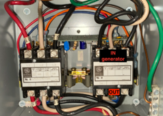
The inverter is designed for both single and split phase input. If your generator is 2 pole 120VAC in phase, then you just connect both hots to L1 and N to N (or per the transfer switch as in the video) to get 60A.


This youtube video explains the issue & the fix. it works on mine after this mod...

He describes my recommendation. He confirmed it's a 2 pole 120VAC generator and connected both poles to L1.
 
The inverter is designed for both single and split phase input. If your generator is 2 pole 120VAC in phase, then you just connect both hots to L1 and N to N (or per the transfer switch as in the video) to get 60A.


He describes my recommendation. He confirmed it's a 2 pole 120VAC generator and connected both poles to L1.
Confirming meaning the voltages were identical and the voltage between phases is zero? I don’t see any real clarification in the generator manual. I will test it today. Thanks!
 
Confirming meaning the voltages were identical and the voltage between phases is zero? I don’t see any real clarification in the generator manual. I will test it today. Thanks!

Yes. Both poles should have a Hot/Line, "L" and a neutral "N" (there might be one common neutral)

Both hots should be 0V to each other.
Both N should be 0V to each other.
Both hots should be ~120V to each N.

The fact that the generator is listed as a 120V model implies both 120V outputs are in phase with each other.

MultiPlus II's pass-through relay is limited to 50 amps.

Good find.

@caymaanedge, this means that you can't pull 60A from the generator into the Multiplus L1. You would want to set your AC input limit to 45A or so.
 
45Amps is fine, I draw slightly under 30amps with both AC’s and fridge, but the generator breaker trips on occasion.

I confirmed L1 and L2 voltage are the exact same and the voltage between L1 and L2 is 0.0
So I ordered a Burndy BIT4 to splice the legs together on the line side of the ATS.
 
45Amps is fine, I draw slightly under 30amps with both AC’s and fridge, but the generator breaker trips on occasion.

I confirmed L1 and L2 voltage are the exact same and the voltage between L1 and L2 is 0.0
So I ordered a Burndy BIT4 to splice the legs together on the line side of the ATS.

Assuming you also have 50A shore power input capability, that's split phase, and the RV ATS should pass shore L1 to inverter L1, N to N and L2 to L2. This will provide 50A on L1 for the inverter and charger, and then it will directly power up to 50A for any devices on the L2 side of the AC panel (2nd A/C unit, etc.).

while fuses and breakers really should only be run to 80% rated, I suspect that running the ATS to its maximum rated current will not be an issue. I would still set AC input limit to no more than 48A just to give a little wiggle room.

Your inverter also has powerassist where it can boost power on the L1 line if the AC input current limit is exceeded.
 
Pretty much I just need to jumper the L4 and L6 wires in my transfer switch to get the 50amp generator to fully work?
 

Attachments

  • Screenshot 2024-03-04 at 9.42.05 AM.png
    Screenshot 2024-03-04 at 9.42.05 AM.png
    2.3 MB · Views: 14
Back
Top