diy solar

diy solar

My first PV System

Don't let these students get their hands on lithium polymer :ROFLMAO:

Are they aware and disciplined in AGM battery safety, specifically high current? (also, the AC voltages from inverter)
It can weld wrenches and jewelry. We get away with working on stuff for years until we make a mistake. I was just hospitalized for a 230VAC shock, and I have professional qualifications and 50 years experience.

Here's valuable advice, some developed in hindsight.

Get insulated handle wrenches so battery terminals can be connected without possibility of bridging to another. Placement of batteries can be optimized to maintain spacing.

Get or make insulated terminal covers. One guy 3D printed them. I used heater hose, and discovered later that is electrically conductive (a hazard at line voltage, but not a bad solution for low voltage batteries.)

Get a portable GFCI and use on output of inverter (or install in attached junction box, discouraging bypass.)

Connect redundant external ground strap to all AC equipment.
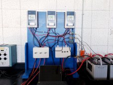
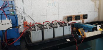
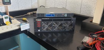
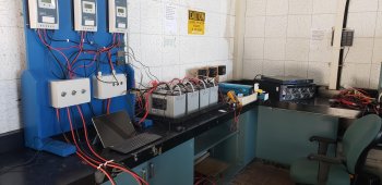
I got pulled into this because when I was providing measurement support to the students, I was concerned with how the student was loading the system (he just put a bunch of space heaters, and light bulb banks and fans on the extension cords) , and he was using bolts instead of bus bars, he had circuit breakers and switches taped to the table top, the wire gauge he was using between the batteries and the inverter were insufficient. So once he cleared his thesis, I got with my boss and we designed a better system with combiner boxes, bus bars and I upped the gauge of the wire from 4 gauge to 00 gauge between the batteries and the inverter, put 2 gauge between the controllers and the batteries and used 2 gauge jumpers between the batteries. Not optimal but an improvement. I designed a 1500 watt electronic loading system for the system so the student could dial up what he needed without using damned space heaters. Everyone was telling me that I couldn't use DC electronic loads on the inverter and I told them that the DC power supply and the Electronic Load both plug into the inverter therefore they are using the inverter AC to power up, so when a student uses the electronic load, the batteries are seeing the total of the inverter, DC power supply, electronic load and whatever load is dialed up on the system. So a 1000 watt load dialed up actually gives the student almost 1500 watts on the batteries. The only problem I eventually ran into was the portable solar panel mounts, but...since the roof is now being worked on, I have 4 months to come up with a good mounting system that can be disassembled each day and stored in the lab. I completed the lab build so I will post a picture...I did post an almost complete picture on another thread, but it's finished now.
 
Sounds good, but go back and review it from a safety perspective.
I think of making thing fool proof, forgetting that I myself am the most talented fool.

Fast DC fuse on battery, covered terminals, grounding, GFCI shock protection.

The setup could be a chance to teach AC wiring to code.

With full-wave rectifier, the electronic load may accept AC on its terminals, depending on specs. That could be a PF = 1.0 load.

For some purposes, it might ideally circulate power back to battery (for inverter tests.) In that case your setup of inverter powers electronic load could work with DC output going to a battery charger. In this case, PF will be lower than 1, whatever electronic load draws from AC source draws while delivering constant DC power. Might be near 1 if its power supply is PF corrected, or could be a rectifier/capacitor front end.

The inverter efficiency for various load types and power factor would be an important part of the study. I think these are spec'd into ideal resistive load, but losses go as I^2 and people here report twice the expected loss (round trip for an AIO with lithium battery.)

This is expandable by replacing the switches/breakers with higher values (already on hand) This is a base system that the student would modify depending on what the professor assigns them. One thing for sure, is by the time I retire in 4 years, I will have advanced my basic knowledge of solar systems. Maybe.

20230405_115132_04.jpg20230405_115201.jpg20230405_115220.jpg20230405_115244.jpg
 
First standard feedback is rearrange cable connections to batteries, so resistance distributed current equally between them.
Positive off one end, negative off the other, would be an improvement. Perfect for 2, not perfect for 4. If you do it for 2 groups of 2, then do it to the 2 groups, that is perfect.

Except if your batteries differ in condition, they will draw different current. So fully charge in parallel, disconnect and settle a few hours, then measure voltage. If some go low, consider equalization.
The batteries are being replaced so that will be a good opportunity to ponder your input because that was something I was pondering when I was making measurements. I have battery output on one end and battery input on the other.....when it is time I will draw up a podunk diagram to make sure we are talking the same language...maybe I can PM or.....I can bring this over to my other thread rather than continue to hijack this thread. (bad Frankie) Thanks Hedges and the rest of the crew for providing some great input to my learning curve.
 
not PM, but look up the resources on the form regarding how to connect batteries series/parallel and search for threads discussing it.
There is a Victron document showing and explaining.
(hint: It is obvious from ohms law what is good vs. bad, just a bit of a complicated network to analyze.)

Wiring both (or multiple) configurations and measuring current in/out of each battery with a clamp ammeter should be part of the student's lab work.
 
The batteries are being replaced so that will be a good opportunity to ponder your input because that was something I was pondering when I was making measurements. I have battery output on one end and battery input on the other.....when it is time I will draw up a podunk diagram to make sure we are talking the same language...maybe I can PM or.....I can bring this over to my other thread rather than continue to hijack this thread. (bad Frankie) Thanks Hedges and the rest of the crew for providing some great input to my learning curve.
I forgot to mention that I do have an 8 way fuse box that I can wire in and use blade fuses
not PM, but look up the resources on the form regarding how to connect batteries series/parallel and search for threads discussing it.
There is a Victron document showing and explaining.
(hint: It is obvious from ohms law what is good vs. bad, just a bit of a complicated network to analyze.)

Wiring both (or multiple) configurations and measuring current in/out of each battery with a clamp ammeter should be part of the student's lab wo
The way I have the batteries hooked up to the charge controllers and the inverter, might explain some of the odd slight voltage drop/differences I am seeing between various measurement points. I believe I left myself enough room to stretch one of each side over to the other side. One thing I noticed right off the bat when I entered this whole solar/battery world is the difference in accuracy between two cheap chinese voltmeters may not seem like a big deal if one is say...0.2 volts different than the other (less than 2 percent), but when you are talking about voltage ranges and measurements between 12.3 and 12.8 volts, IE, you think your battery is at 50 percent but in reality it is closer to 60 percent (or 40 percent), so a 2 percent voltage accuracy error can make a 10 percent difference in capacity. OK...I am rambling now.
 
Back
Top