diy solar

diy solar

Mystery BMS

MrNatural22

?SW sunshine =⚡️⚡️lit up thru the darkness✌️
Joined
Sep 20, 2019
Messages
1,662
Location
1000 miles to somewhere
@willprowse on Wills latest video on YouTube “Lithium battery mystery” within a link to the Ruixu 100amp LiFePo there also is a 100amp 4s BMS listed that resembles the large BMS that was in the initial Ruixu sent for testing. Curious if that may be one in the same BMS in the tested Ruixu drop in before the punny cheap one was used?
Take a peek ?

https://www.ruixubattery.com/12v-100ah-lithium-iron-phosphate-battery-cell

75205E37-053D-468F-BC00-0AB30E843D39.png
 
That's the BMS I was sent with 200 Ah cells from Ruixu. What they *didn't* include is any documentation on the BMS, or direction on how to wire it. So while I have a BMS in hand that may possibly fit my needs, it looks like I need to buy a different BMS in order to have one that I can use safely and properly.
 
That's the BMS I was sent with 200 Ah cells from Ruixu. What they *didn't* include is any documentation on the BMS, or direction on how to wire it. So while I have a BMS in hand that may possibly fit my needs, it looks like I need to buy a different BMS in order to have one that I can use safely and properly.
Very simple and easy to connect to your cells. Search the forum for information.
Here is a different bms but same connection process
 
Last edited:
Thanks for sharing. I tried searching the forum and YouTube yesterday for my particular BMS. That's how I found your post. And there is an Orient Power YT video showing the BMS wiring, but very basic.

I think my questions go a bit beyond the particular BMS in the video. For example:
  • There are 6 wire mounting holes on the B- side of the BMS. Do I need to wire all six to the battery negative terminal, or just any one of the six? Will's site shows a BMS example like that with 3 BMS wires all wired to negative. But I don't understand why.
  • There are 6 wire mounting holes on the P- side of the BMS. They are labeled, left to right, as C-1, P-9, P-8, P-7, C-2, C-3. I get that I need a P- to go to load, and a C- to go to charger. But do I need to wire all three of each? If not, does it matter which of the three I wire? And they all seem to be connected on the board anyway. And why are they labeled that way? P-7? C-1 next P-9?
  • There is also a B+ terminal. Presumably wired to battery positive. But what does it do? Most BMSs don't seem to have this. And it is separate from the positive cell sensing leads.
  • And that's just wiring. To say nothing of the calibration - high cell voltage cutoff, low cell voltage cutoff, temp cutoff...
1588025579517.png1588025664232.png

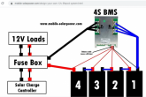
An example of what I see with multiple BMS wires to the same terminal. And it is also on other sites, not just Will's. Is there a reason for this wiring?
1588026558637.png
 
Last edited:
Do I need to wire all six to the battery negative terminal, or just any one of the six?
The answer depends on your charge current. The charge current will dictate how "much" wire you need to run to your battery, in terms of how big each wire you solder on there is and how many you need to carry that current.

If you run 10awg wires from you BMS you will need more than if you used 6awg wire.
All 6 holes are connected, they are just optional mounting locations.
 
Wires you solder to the B- side (how many you choose depend on what current you’ll be using as MrSandals said, I have three 8g on each side on mine) they will be joined together in a ring type terminal and go to the main
battery negative.
Some BMSs come wire these already attached but some don’t like yours.
The replacement for the cheap one Ruixu tried to use on the WP exposed Ruixu switcheroo escapade of the past I received from Ruixu had them already. Yours looks like the same 100a BMS I have but looks can be deseptive. ?
The same size and amount of wires will be soldered to the P- side of the BMS then joined together in another ring terminal and will be the negative connection to the load or the negative side of the fuse box. Like in the picture you posted.
The 5 small wires are the balance leads that require small ring connectors and attach in the correct sequence also as shown in your picture.
 
Last edited:

diy solar

diy solar
Back
Top