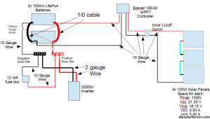
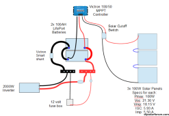
I currently have a 12v system and am working on upgrading it (finances are an issue so it won't all be upgraded at once). The diagram below is mostly how it is currently set up, but the diagram contains components I currently do not have on the system yet. This will be installed in a minivan (which I live in).
The components different from the diagram:
One battery installed rather than two.
The current inverter is a 1000 watt P/S not the 2000 watt on the diagram.
I don't yet have the smart shunt, the solar cutoff switch, nor the buss bars.
The small grey circles near the positive buss bar are fuses, which I haven't determined the size of as yet.
I should probably point out that I am also considering changing the charge controller to a Victron Smart 100/50, though I haven't completely decided on that yet.


