diy solar

diy solar

Need help with Heltec BMS on new system

offgridpower

Off Grid Simple Living AZ
Joined
Nov 19, 2020
Messages
22
I just fired up my new system, but I have had to bypass the BMS because I can not get it to turn on. The BMS is a Heltec B1A24S15P 150A model. Before powering up the system I was seeing a voltage drop through the BMS, from 53V at the batteries to 34V on the other side of the BMS. When I opened the breaker to the batteries to power up the system, the voltage dropped to 9V. Also, the BMS will not power on. It has an power indication light that should light up. The manual said that it needs a 5V differential between the controller and the battery for it to stat up. How does one go about creating the necessary differential? I thought that the BMS would just power up once the MPPT controller started charging, but the controller cannot start up with only 9V.

This is the problem, how do I get 5V differential if the BMS will not let enough current through to start the controller? Also, should the BMS be restricting current when it is not turned on?

Any help would be greatly appreciated. I currently have a bypass in place and the system is operational, just without the BMS.

Trouble shooting so far: I have went through and double checked the individual cell wiring to the BMS, it is all wired up orrectly according to the factory diagram for a 16 cell battery.
 
I just fired up my new system, but I have had to bypass the BMS because I can not get it to turn on. The BMS is a Heltec B1A24S15P 150A model. Before powering up the system I was seeing a voltage drop through the BMS, from 53V at the batteries to 34V on the other side of the BMS. When I opened the breaker to the batteries to power up the system, the voltage dropped to 9V. Also, the BMS will not power on. It has an power indication light that should light up. The manual said that it needs a 5V differential between the controller and the battery for it to stat up.

Are you talking about the BMS or the charge controller for the 5V differential? The way you've worded it sounds like the BMS, but that sounds like the requirement for a Victron SCC, and the differential is between the battery voltage and panel voltage, which is usually trivial to attain.

How does one go about creating the necessary differential? I thought that the BMS would just power up once the MPPT controller started charging, but the controller cannot start up with only 9V.

This is the problem, how do I get 5V differential if the BMS will not let enough current through to start the controller? Also, should the BMS be restricting current when it is not turned on?

Any help would be greatly appreciated. I currently have a bypass in place and the system is operational, just without the BMS.

Good to know that works.

Trouble shooting so far: I have went through and double checked the individual cell wiring to the BMS, it is all wired up orrectly according to the factory diagram for a 16 cell battery.

Bad sense wire crimp, connection at the BMS, bent pin, or the BMS itself. Did you confirm correct harness voltage measurements at the BMS end? If so, you may have a bad BMS.

DALY BMS require you to short the B- to the P- to "activate" the BMS. Not sure if the Heltec needs the same.
 
When I first connected my Heltec (JK BMS) I had a similar issue. The BMS seemed dead, would not do anything. This is a normal condition when they are new and connected for the first time. But it is not well explained. You need to supply a charging voltage that is at least 5 volts higher than the battery voltage. This is what made it very hard for me at first as my battery was near full charge so my CC CV charger was sitting just 2 volts higher. It would not turn on.

After thinking about it, I found a trick that works every time.
The BMS requires a voltage on the P- lead that is 5 volts more negative than the B- lead. I now use one of my RC car batteries (I think a regular 9 volt battery would work) and a light bulb to limit the current. Connect the positive side of the extra battery to the negative terminal of your battery bank and B- lead going to the BMS. Then connect the positive side of the extra battery through a light bulb to the P- output lead of the BMS. This will turn on the BMS and depending on the mode and settings, it might turn on the protection MOSFETS, which will short the B- to P- which is why I use the light bulb so it does not short my RC car battery. Worst case, the bulb lights up. It will beep, and the blue tooth led will start flashing. Now connect with the app and setup the battery parameters. Then shut it down and power it up again (might need the extra battery again) for it to use the new settings for the number of cells etc. When it powers up with a new number of cells, it does a self test where it runs the balancer on each cell and measures the wire resistances. Let it complete that before you put a load or charge current on the system. Most likely it will be done by the time you get the blue tooth connected.

I have disconnected mine a few times, and if it is not off long, and the battery is not full, it seems to come on without a problem, but I have had to use the extra battery a few times too. I guess it has to do with what state it was in when the battery was disconnected. If the battery is more than 5 volts below your charger setting, it will just power up without an issue also.
 
Are you talking about the BMS or the charge controller for the 5V differential? The way you've worded it sounds like the BMS, but that sounds like the requirement for a Victron SCC, and the differential is between the battery voltage and panel voltage, which is usually trivial to attain.


Good to know that works.


Bad sense wire crimp, connection at the BMS, bent pin, or the BMS itself. Did you confirm correct harness voltage measurements at the BMS end? If so, you may have a bad BMS.

DALY BMS require you to short the B- to the P- to "activate" the BMS. Not sure if the Heltec needs the same.
Thanks, I will definitely check for bad connections or bent pins. I am still trying to figure out how to turn the BMS on though. It requires a 5V differential across the BMS to turn on. The voltage needs to be 5 volts higher on the P- side than on the B- side. I cant figure out a way to do it while it is connected to the system. The batteries average 53 volts and the controller puts out just a little more than that.
 
When I first connected my Heltec (JK BMS) I had a similar issue. The BMS seemed dead, would not do anything. This is a normal condition when they are new and connected for the first time. But it is not well explained. You need to supply a charging voltage that is at least 5 volts higher than the battery voltage. This is what made it very hard for me at first as my battery was near full charge so my CC CV charger was sitting just 2 volts higher. It would not turn on.

After thinking about it, I found a trick that works every time.
The BMS requires a voltage on the P- lead that is 5 volts more negative than the B- lead. I now use one of my RC car batteries (I think a regular 9 volt battery would work) and a light bulb to limit the current. Connect the positive side of the extra battery to the negative terminal of your battery bank and B- lead going to the BMS. Then connect the positive side of the extra battery through a light bulb to the P- output lead of the BMS. This will turn on the BMS and depending on the mode and settings, it might turn on the protection MOSFETS, which will short the B- to P- which is why I use the light bulb so it does not short my RC car battery. Worst case, the bulb lights up. It will beep, and the blue tooth led will start flashing. Now connect with the app and setup the battery parameters. Then shut it down and power it up again (might need the extra battery again) for it to use the new settings for the number of cells etc. When it powers up with a new number of cells, it does a self test where it runs the balancer on each cell and measures the wire resistances. Let it complete that before you put a load or charge current on the system. Most likely it will be done by the time you get the blue tooth connected.

I have disconnected mine a few times, and if it is not off long, and the battery is not full, it seems to come on without a problem, but I have had to use the extra battery a few times too. I guess it has to do with what state it was in when the battery was disconnected. If the battery is more than 5 volts below your charger setting, it will just power up without an issue also.
Thanks for your reply, I could try to put somthing like that togather to test the BMS on the bench , but I am still confused on how to create that 5 volt difference across the P- and the B- while it is attached to the system. The battery is usually between 52 and 54 volts, and the controler only creates a little higher voltage than that, so it does not naturally see a differential. How can I temporarily introduce 60 volts (54 + 5) to the P-side?
 
Thanks for your reply, I could try to put somthing like that togather to test the BMS on the bench , but I am still confused on how to create that 5 volt difference across the P- and the B- while it is attached to the system. The battery is usually between 52 and 54 volts, and the controler only creates a little higher voltage than that, so it does not naturally see a differential. How can I temporarily introduce 60 volts (54 + 5) to the P-side?
Do you have a disconnect switch or breaker between the charge controller and the BMS? If you do, just turn that off until you get the BMS powered up. Your battery bank is already supplying 54 volts. Just add a 9 volt battery on the negative end. That will give you 63 volts, which will work fine. Connect the positive side of the 9 volt to the negative end of the cells, the B- lead of the BMS. Then connect the negative side of the 9 volt battery to the P- lead of the BMS. That will wake it up. With a 9 volt, it won't push much current, once you hear the BMS beep, you can disconnect it. I used a high power RC car battery, but it did not seem to need much current. I had the light bulb in series just in case the BMS output switch turned on. On a first power up, it will be off until you turn it on in the app.
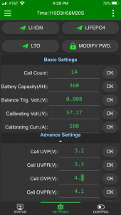
Here is the basic settings page from the app.
IMG_8593.PNG
You need to set the number of cells, and choose the type of cells at the top. In the advanced section, you can fine tune the settings to your cells.
Once that is set, go to the control page.
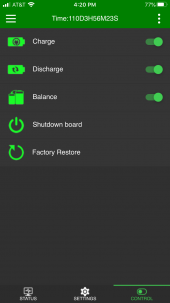
Here is the control page from the App.
IMG_8594.PNG
On first power up, the three switches will be off.
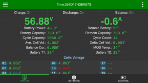
If you changed the number of cells, click the "Shutdown Board" button and then use the battery to power it up again. Then check the status page. Here is mine.
IMG_8962.PNG
Make sure the voltages all look good. Also scroll down and check the wire resistance readings. They should all be pretty close. The cell voltage in red is the lowest, and the blue is the highest. Across the top you have the Charge: Discharge: and Balance: functions. Go back to the control page and turn on the functions. Then you should be able to turn on the charge controller and inverter and test it out.
 
Do you have a disconnect switch or breaker between the charge controller and the BMS? If you do, just turn that off until you get the BMS powered up. Your battery bank is already supplying 54 volts. Just add a 9 volt battery on the negative end. That will give you 63 volts, which will work fine. Connect the positive side of the 9 volt to the negative end of the cells, the B- lead of the BMS. Then connect the negative side of the 9 volt battery to the P- lead of the BMS. That will wake it up. With a 9 volt, it won't push much current, once you hear the BMS beep, you can disconnect it. I used a high power RC car battery, but it did not seem to need much current. I had the light bulb in series just in case the BMS output switch turned on. On a first power up, it will be off until you turn it on in the app.
Here is the basic settings page from the app.
View attachment 46185
You need to set the number of cells, and choose the type of cells at the top. In the advanced section, you can fine tune the settings to your cells.
Once that is set, go to the control page.
Here is the control page from the App.
View attachment 46183
On first power up, the three switches will be off.
If you changed the number of cells, click the "Shutdown Board" button and then use the battery to power it up again. Then check the status page. Here is mine.
View attachment 46186
Make sure the voltages all look good. Also scroll down and check the wire resistance readings. They should all be pretty close. The cell voltage in red is the lowest, and the blue is the highest. Across the top you have the Charge: Discharge: and Balance: functions. Go back to the control page and turn on the functions. Then you should be able to turn on the charge controller and inverter and test it out.
Awesome, that makes sense, I will give it a try! ?
 
Do you have a disconnect switch or breaker between the charge controller and the BMS? If you do, just turn that off until you get the BMS powered up. Your battery bank is already supplying 54 volts. Just add a 9 volt battery on the negative end. That will give you 63 volts, which will work fine. Connect the positive side of the 9 volt to the negative end of the cells, the B- lead of the BMS. Then connect the negative side of the 9 volt battery to the P- lead of the BMS. That will wake it up. With a 9 volt, it won't push much current, once you hear the BMS beep, you can disconnect it. I used a high power RC car battery, but it did not seem to need much current. I had the light bulb in series just in case the BMS output switch turned on. On a first power up, it will be off until you turn it on in the app.
Here is the basic settings page from the app.
View attachment 46185
You need to set the number of cells, and choose the type of cells at the top. In the advanced section, you can fine tune the settings to your cells.
Once that is set, go to the control page.
Here is the control page from the App.
View attachment 46183
On first power up, the three switches will be off.
If you changed the number of cells, click the "Shutdown Board" button and then use the battery to power it up again. Then check the status page. Here is mine.
View attachment 46186
Make sure the voltages all look good. Also scroll down and check the wire resistance readings. They should all be pretty close. The cell voltage in red is the lowest, and the blue is the highest. Across the top you have the Charge: Discharge: and Balance: functions. Go back to the control page and turn on the functions. Then you should be able to turn on the charge controller and inverter and test it out.
I worked!! I used your method to connect a regular 9V battery and it started right up. Thanks for your help!!
 
Glad you got it up and running. I have not had to shut my system down much, but if I have to again, I may wire in a socket for doing the startup.
 
Back
Top