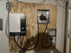
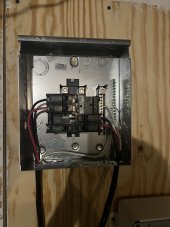
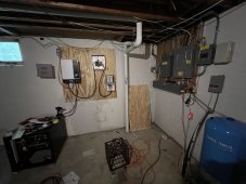
Hello this project started late August, I had the panels ground mounted for a couple of weeks but just getting started on this. So I have a couple of questions and please point out all many things I’m doing wrong. But the main reason I am currently posting is because I’m getting voltage on the Ground in the load box. I am not currently grounded to house. I have been this doing phases, at this point I have 220 volts/ 2K watts of solar outside, batteries up and talking to inverter. The batteries are being charged from 50 ish perecent for the 1st time but inverter is switched off and as you can see no loads on it yet. I have seen many all the videos I could find about wiring the transformer, currently doing this method of it’s own 50 amp breaker. I would assume that the voltage is coming from the ground wire I have connected from the inverter. Eventually I will adding a critical load panel but for know I want to run this as a power backup to start. I will adding a 20 amp outlet here at the inverter.
1- So how do I get rid of voltage so touching the panel is safe? Disconnect ground from the inverter? I plan to pulll power back over for pass through eventually. If I run a ground wire from main house panel to here would that solve this for now?
2- the Growatt 5000 is switched off but is seeing Solar and says it’s charging my batteries but is it charging them at the same rate as if the inverter was turned on? I ask because I have only seen like a 3 percent raise in and they have been under charge for a couple of hours now. I know there are lots of factors involved.
Thanks for reading and the help.