diy solar

diy solar

New Active balancer

I've checked it many times, but never with a 500mV delta. I think with a 200mV delta one time I got something between 1.5A and 2A. I only know that it has worked well to get the diff down to 1 or 2 mV at rest.
1.5A to 2.0A with a delta of ~200mV is pretty much spot-on (and 2.5 to 3 times what you’d get with the typical passive balancing integrated into the average BMS).

What I like about Heltec’s active balancer is that it functions all the way down to 2.9V (compared to typical BMS passive Balancers which are only active above 3.55 or 3.50V).

That means the Heltec Active Balancer can be used for Bottom Balancing (which is better for a time-shift PV application like mine ;)).
 
I’m not certain but can guess (EE background):

1/ Charge a capacitor in parallel from each cell (probably all three capacitors in parallel, not sure).

2/ Now disconnect each capacitor from its cell.

3/ Now short all of the capacitors together, settling to average of cell voltages (capacitors associated with any cells above average voltage will decrease, capacitors associated with any cells below average voltage will increase, capacitors associated with any cells exactly at average voltage will see no change).

4/ Open the connection between capacitors so that each capacitor (or bank of 3) is isolated from the others.

5/ Now reconnect each capacitor (or bank of 3) to its corresponding cell again which will inject some charge into all low cells and will remove some charge from all high cells (and will leave cells at average voltage unchanged).

Now go back to step 2 and repeat that cycle endlessly…

Once all cells are at the average voltage (balanced) there will no longer be any charge transferring into or out of the capacitor bank…
Interesting way to balance. Sounds reasonable, but may be a little bit inefficient.

Suppose we charge a 100uF cap up to 100v. We then connect this charged cap to another 100uF cap that is totally discharged. The end result is 200uF at 50v. The initial energy in the 100uF cap is twice the energy in the resultant 200uF capacitor. Where did the energy go?

I expect there may be some energy lost while balancing, but not so much to worry about.
 
Is this thread about BMSs or Active Balancers.
The thread is not about Active Balancers. The thread is about the particular active balancer introduced in the first post. The fact is that you started going off topic with your active balancers so just calm down.
 
The thread is not about Active Balancers. The thread is about the particular active balancer introduced in the first post. The fact is that you started going off topic with your active balancers so just calm down.
If this thread has morphed into an owner’s thread, I’ll step out…
 
If this thread has morphed into an owner’s thread, I’ll step out…
You "morphed" it. You were the first post that took it off topic so dont criticize others if they do the same thing.
 
I emailed them from their github page. Looks like they will have a 12v/24v option soon. May want to wait for that instead of wiring up an external power supply.
I was really annoyed with myself for not having checked into this. Its not worth trying to cancel the order though. Ill just live with it for the occasional times I connect it and re-top balance.
 

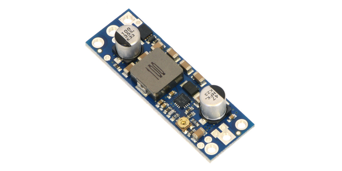
i have had good experience with pololu regulators.

this one can be adjusted to 30V output and accepts as low as 2.9V
This one maxes out at 30v and the balancer requires a minimum of 30v. I tried clicking on the variant link and it looks like this line doesn't offer anything with a higher output. Am I dumb being concerned that it might not work if the regulator didn't just quite make it to the threshold to operate the balancer?

I was planning to buy 4 dirt cheap 9v batteries once a year (or as required) and connect them in series for a 36v battery. If something like in your link was available for $25 I would certainly consider that.
wise to be doubtful that hitting the absolute minimum voltage will be enough.

can’t offer reassurance due to sharing a similar concern. that’s the highest voltage one they have.

someone mentioned 10S and me mental logic was that if it really works with 10S LiFePO4 then 2.5Vpc should be expected to work, that would be 25V. then 3.0Vpc should be ok, 10*3.0 30V.

won’t be testing it because i’ve already got a BMS set up
 
The DC to DC boost storage is 7.5 F's (not uF). It is more like a boost dc-dc converter from highest voltage cell to a storage battery that is used to feed buck converter to dump to lowest voltage cell.

The main advantage of this unit is it allows you to set balancing to above a cell voltage minimum voltage. For many DIY'er cells, lacking good cell matching, when high current is drawn by inverter the individual cells' voltage slump varies due to poor cell matching. Any balancer operating during the slump voltage difference will react to the cell slump difference possibly balancing in direction that will result in greater cell voltage mismatch near full charge point where cell voltage balance is critical to avoid overvoltage BMS shutdown during charging.

If you don't have perfectly matched cells, with same voltage slump with moderate discharge current, it is better to restrict balancing to cell voltage above 3.4v where cell state of charge voltage will be easier for balancer to detect and push in desired direction. Then it is a race to balance cells before one overvoltages during charging. This is where having the greater balancing current is an advantage.
 
If you don't have perfectly matched cells, with same voltage slump with moderate discharge current, it is better to restrict balancing to cell voltage above 3.4v where cell state of charge voltage will be easier for balancer to detect and push in desired direction. Then it is a race to balance cells before one overvoltages during charging. This is where having the greater balancing current is an advantage.
Agree 100%. Personally, the one I bought will never even be connected except for occasionally when there is an apparent "unbalance" at which point I will charge to a 3.65v high voltage disconnect with the balancer connected using the high current charger and then connect a power source and continue with a low current charge to balance everything. Once balanced, return to using somewhere around 3.4v as the high voltage disconnect.
 
My first battery bank is using this type of active balancing. I originally had it set to run balancing all the time when the cells are over 2.9 volts. My cells are NCM and I never run them below 3.5 volts, but that is similar to running LFP down to 3.1 volts. The way my battery is built, I have the wide factory buss bars tying the cells together, except for between cell 10 and cell 11 where it has a fairly short (under 18 inches or 0.5 meter) #2 awg cable. At 80 amps, this junction does drop about 6 mv more than the short and wide buss bars. This was certainly causing the balancer to kick in and try to pull up both cells 10 and 11I can certainly see this actually causing the cells to be pushed out of balance.

I have made 3 changes to stop this from happening. The first big one is setting the BMS balance threshold to a little higher than the difference I am seeing due to the greater voltage drop on the cable vs the buss bars. The more equal all of your buss bars are, the less important this will be. My second step was paralleling a second cable, but I didn't have more #2 so I used a #4 cable. That was enough to reduce my voltage drop difference to only 5 mv. So I set the balancer to 0.008 or 8 mv. Then the last change I made, was it only balances when the cells are above 3.6 volts. That would be like 3.2 on LPF cells, but LFP has a much flatter curve in this area, so setting it up to more like 3.3 or even 3.4 volts may work better.

The one issue I see when working with LFP cells, is that you do need to run them over 80% charged o get above the knee to get a good top balance. From 20% to 80% charged, the voltage of LFP cells changes so little, it is really hard to ensure their true state of charged is balanced.

The biggest take away I get from a lot of the battery balancing talk is that there is no replacement for well matched cells. In my case, even a tiny resistance of under 0.002 ohms is enough to make the balance see a difference. As it turns out, my cells are incredibly well matched to each other, so balancing on this pack has never been an issue, but my cheaper E-Bike battery is a completely different story. I know that pack has 2 cells that are weaker than the rest, and no amount of balancing is going to keep them from being the runners on both ends of the charge curve. Solar storage, and E-Bike power are completely different use cases. I found that bottom balance on the E-Bike is far more important, because I do run it down until it quits quite often. So I bottom balanced as good as I could with those two weak cells, but then I have to terminate charge when those two become full. The rest of the cells never exceed 85% charge. I don't want to use a balancer on that pack any more, because it pulls those weak cells down. I need them full. Ideally, it would possibly help range, if a balancer could push energy to those weal cells when they start to get low, but that is the opposite of a balancer running only above a set voltage. The BMS I use on the E-Bike now is just a dumb one that shuts off when a cell goes low, and only has a weak 30 ma balance, that I never hit as it does not pull down until a cell goes over 4.15 volts.

The real sad part about cells that are not well matched is that the matching will typically only get worse. If there is a cell with only 85% capacity, that weak cells is being forced to work much harder. With perfect balancing, the weak cells is being pushed higher and pulled lower on every charge cycle. I think the problem can be reduced for Solar Storage use with a solid top balance, and making sure the weakest cells only go up t 85-90% and don't go below 40%. The stronger cells will still run in a smaller range, but this should maximize the life of the weak cell.

I have not tried this yt, but when I was looking at the 280 AH LFP cells, my thought was to add smaller LFP cells in parallel to bring up the capacity of any cells that measured lower capacity. Just a 3% capacity difference on a 280 AH cell would be an 8.4 AH difference in capacity. You can easily find 18650 LFP cells in capacities of 1 AH to 3.5 AH. So you just parallel a few 18650's to get the total cell capacities to match up. Maybe even over shoot a little so the already weak cells ends up cycling a little less. Tack on 3 x 3 AH cells, and you get 0.6 AH more than the true measured 280 AH cell.
 
I've checked it many times, but never with a 500mV delta. I think with a 200mV delta one time I got something between 1.5A and 2A. I only know that it has worked well to get the diff down to 1 or 2 mV at rest.
How long did the heltec balancer take to balance from the 200mV delta to your current 1-2 mV? Also what size battery is it balancing?
 
How long did the heltec balancer take to balance from the 200mV delta to your current 1-2 mV? Also what size battery is it balancing?
I've done it with 25Ah cells and 230Ah cells, 8S 24V in both cases. I don't seem to have notes on how long it took, but I think that is partially because I often get distracted doing other stuff, and when I come back I just notice they are all within 1-3mV. Sorry I don't have anything more specific.
 
I've done it with 25Ah cells and 230Ah cells, 8S 24V in both cases. I don't seem to have notes on how long it took, but I think that is partially because I often get distracted doing other stuff, and when I come back I just notice they are all within 1-3mV. Sorry I don't have anything more specific.
I’ve used mine to bottom balance connecting the balancer overnight after LVD and disconnecting the next morning as solar charging starts.

Let’s call it 8-10 hours of balancing per day and it took 3-4 days (so 25-40 hours total) to balance one cell that was ~100mV above the others around 3.0V (so ~3% SOC difference).

The ~100mV did not remain through the entire 25-40 hour period, but assuming it did and that 100mV of delta translates to 1A of balance current, that would mean 25-40Ah of balance charge, or 4.5 to 7.1% of my 560Ah battery.

So average balance current over the full balance period probably averaged 40-60% or 0.4-0.6A…

Overall, very happy with how it performed.
 
Back
Top