diy solar

diy solar

New Lux Power LXP-LB-US 12k / GSL-H-12KLV-US with 200A AC Passthrough Current (US Market)

Status
Not open for further replies.
Awesome! If you can share portions of the ESP32 code, I'm going to do something very similiar. Only potential hiccup/modification is that I might try to go: CircuitSetup ==> ESP32 (at Mains), parallel post to emoncms/HA ==> MQTT ==> ESP32 (in powershed) ==> LXP

If the MQTT +Wifi isn't fast enough (even if I offset 500W or something so that I don't ever backfeed), I might do a longer RS485 network (wired).

I think I found the right register mapping for SDM, but would appreciate knowing what the minimum required registers are, and that I'm populating the right ones. I haven't ordered my LUX yet, so bench testing/planning are in order.

Thank you!
@elusivesd Any luck on finding the source code? I just want to double check the required registers. My Lux 12k is here now, but want to bench test prior to final installation. Thanks!
 
When the voltage gets down to 49 V in the battery the battery kicks off goes into trouble and it de-couples from the inverter. what is the suggested low-voltage? if I’m supposed to have 48 V is that what you mean by discharging it fully? I am assuming that it’s actually de-coupling in the inverter when it reaches that voltage

Don't discharge fully, only enough that it could use all available PV power.
 
Lots of back and forth

So I finally figured out what was going on with the battery. Since I only had one battery the charge and discharge rates had to be brought down to 50-70 amps otherwise the battery goes into fail mode. The battery has to be software updated and a com cable has to be made I don’t have com’s yet……
 
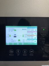
Question: on the display there is a house with a wattage number. Is the wattage number what’s available or what’s being used? I thought what being used but doesn’t make any sense… I only have three led lights on; about 200w yet the display says upwards of 5000watts at times. What’s up
 

Attachments

  • 8CB01E53-4C89-4D2B-B22F-D77F18F3351A.jpeg
    8CB01E53-4C89-4D2B-B22F-D77F18F3351A.jpeg
    707.8 KB · Views: 19
@elusivesd Any luck on finding the source code? I just want to double check the required registers. My Lux 12k is here now, but want to bench test prior to final installation. Thanks!
@edgecrusher - sorry been busy, but yes, I found it. Overall code is embarrassingly bad, but here are the main snippets (removed some custom offset code to help with clarity, some vars may be 'missing').

Main loop, keeping registers up to date:


C++:
#include <ModbusRTU.h>  // https://github.com/emelianov/modbus-esp8266
ModbusRTU mb;

/**
   Task: get time critical energy data
*/

void energyLoop(void* parameter) {
  for (;;) {
    /*Repeatedly fetch some values from the ATM90E32 */
    gValues.realPower = eic.GetTotalActivePower();
    vTaskDelay(10 / portTICK_PERIOD_MS);
  }
}

// helper function, takes float value as input, dumps it into correct register
void float32ToInputReg(float f32, int startReg) {
  const uint8_t* temp = reinterpret_cast<const uint8_t*>(&f32);
  // int value = word(highByte, lowByte);
  int hiregValue = word(temp[3], temp[2]);
  int loregValue = word(temp[1], temp[0]);
  mb.Ireg(startReg, hiregValue);
  mb.Ireg(startReg + 1, loregValue);
}

// main loop
void loop() {
  // RTU Slave: 1, Fn: 04, len: 5, 0 0 0 2 // 0 - Voltage (V)
  float32ToInputReg(gValues.voltage, 0);

  // RTU Slave: 1, Fn: 04, len: 5, 0 6 0 2 // 6 - Current (A)
  float32ToInputReg(gValues.totalCurrent, 6);

  // RTU Slave: 1, Fn: 04, len: 5, 0 C 0 2 // 12 - active power (W)
  float32ToInputReg(gValues.realPower, 12);

  // RTU Slave: 1, Fn: 04, len: 5, 0 12 0 2 // 18 - apparent power (VA)
  float32ToInputReg(gValues.apparentPower, 18);

  // RTU Slave: 1, Fn: 04, len: 5, 0 18 0 2 // 24 - reactive power (VAr)
  float32ToInputReg(gValues.reactPower, 24);

  // RTU Slave: 1, Fn: 04, len: 5, 0 1E 0 2 // 30 - power factor (none/float)
  float32ToInputReg(gValues.powerFactor, 30);

  // RTU Slave: 1, Fn: 04, len: 5, 0 46 0 2 // 70 - frequency (hz)
  float32ToInputReg(gValues.freq, 70);

  mb.task();
  yield();
  // vTaskDelay(10000 / portTICK_PERIOD_MS);
}

Here are some 'notes' I had in my setup section. They are hardcoded values, used for testing/reverse engineering. They may be helpful to you (or not)

C++:
void modbusSetup() {
  Serial1.begin(19200, SERIAL_8N2, 26, 25);  // hardware serial attached to the MAX485 module rxpin, txpin
  mb.begin(&Serial1, 16);                    // RE/DE connected to GPIO 16 of ESP32
  mb.slave(SLAVE_ID);
  mb.onRaw(cbRtuRaw);  // Assign raw data processing callback

  // RTU Slave: 1, Fn: 04, len: 5, 0 0 0 2 // 0 - Voltage (V)
  mb.addIreg(0, 120);
  mb.addIreg(1, 120);

  //* Phase 2 line to neutral Volts
  mb.addIreg(2, 120);
  mb.addIreg(3, 120);

  //* Phase 3 line to neutral Volts
  mb.addIreg(4, 0);
  mb.addIreg(5, 0);

  // RTU Slave: 1, Fn: 04, len: 5, 0 6 0 2 // 6 - Current (A)
  mb.addIreg(6, 1);
  mb.addIreg(7, 12);

  //* Phase 2 current
  mb.addIreg(8, 1);
  mb.addIreg(9, 1);

  //* Phase 3 current
  mb.addIreg(10, 0);
  mb.addIreg(11, 0);

  // RTU Slave: 1, Fn: 04, len: 5, 0 C 0 2 // 12 - active power (W)
  mb.addIreg(12, 3334);
  mb.addIreg(13, 1332);

  // for 3 phase meter only
  // RTU Slave: 1, Fn: 04, len: 5, 0 E 0 2 // 14 - phase 2 active power (W)
  mb.addIreg(14, 3334);
  mb.addIreg(15, 1332);

  // for 3 phase meter only
  // RTU Slave: 1, Fn: 04, len: 5, 0 10 0 2 // 16 - phase 3 active power (W)
  mb.addIreg(16, 3334);
  mb.addIreg(17, 1332);

  // RTU Slave: 1, Fn: 04, len: 5, 0 12 0 2 // 18 - apparent power (VA)
  mb.addIreg(18, 324);
  mb.addIreg(19, 122);

  //* apparent power VA phase 2
  mb.addIreg(20, 324);
  mb.addIreg(21, 122);

  //* apparent power VA phase 3
  mb.addIreg(22, 0);
  mb.addIreg(23, 0);

  // RTU Slave: 1, Fn: 04, len: 5, 0 18 0 2 // 24 - reactive power (VAr)
  mb.addIreg(24, 324);
  mb.addIreg(25, 122);

  //* VAr phase 2
  mb.addIreg(26, 324);
  mb.addIreg(27, 122);

  //* VAr phase 3
  mb.addIreg(28, 0);
  mb.addIreg(29, 0);

  // RTU Slave: 1, Fn: 04, len: 5, 0 1E 0 2 // 30 - power factor (none/float)
  mb.addIreg(30, 0);
  mb.addIreg(31, 95);

  //* pf phase 2
  mb.addIreg(32, 0);
  mb.addIreg(33, 95);

  //* pf phase 3
  mb.addIreg(34, 0);
  mb.addIreg(35, 95);

  // 3 phase meter only.  did not see query for this?
  // RTU Slave: 1, Fn: 04, len: 5, 0 24 0 2 // 24 - phase angle (degrees)
  mb.addIreg(36, 0);
  mb.addIreg(37, 0);

  //* sum of line currents
  mb.addIreg(48, 1);
  mb.addIreg(49, 1);

  //* total system power
  mb.addIreg(52, 155);
  mb.addIreg(53, 155);

  // RTU Slave: 1, Fn: 04, len: 5, 0 46 0 2 // 70 - frequency (hz)
  mb.addIreg(70, 60);
  mb.addIreg(71, 0);

  // RTU Slave: 1, Fn: 04, len: 5, 0 48 0 2 // 72 - Import active energy (kWh)
  mb.addIreg(72, 1);
  mb.addIreg(73, 12);

  // RTU Slave: 1, Fn: 04, len: 5, 0 4A 0 2 // 74 - Export active energy (kWh)
  mb.addIreg(74, 0);
  mb.addIreg(75, 0);

  // RTU Slave: 1, Fn: 04, len: 5, 0 4C 0 2 // 76 - Import reactive energy (kvarh)
  mb.addIreg(76, 1);
  mb.addIreg(77, 12);

  // RTU Slave: 1, Fn: 04, len: 5, 0 4E 0 2 // 78 - export reactive energy (kvarh)
  mb.addIreg(78, 0);
  mb.addIreg(79, 0);

  // RTU Slave: 1, Fn: 04, len: 5, 0 56 0 2 // 86 - maximum total system power demand (W)
  mb.addIreg(86, 545);
  mb.addIreg(87, 545);

  // RTU Slave: 1, Fn: 04, len: 5, 0 58 0 2 // 88 - import system power demand (W)
  mb.addIreg(88, 544);
  mb.addIreg(89, 333);
}
 
Last edited:
Does anyone know if the Mobil LuxPower program is available for pc laptop. If so where can I get it?
 
@edgecrusher - sorry been busy, but yes, I found it. Overall code is embarrassingly bad, but here are the main snippets (removed some custom offset code to help with clarity, some vars may be 'missing').

Main loop, keeping registers up to date:


C++:
#include <ModbusRTU.h>  // https://github.com/emelianov/modbus-esp8266
ModbusRTU mb;

/**
   Task: get time critical energy data
*/

void energyLoop(void* parameter) {
  for (;;) {
    /*Repeatedly fetch some values from the ATM90E32 */
    gValues.realPower = eic.GetTotalActivePower();
    vTaskDelay(10 / portTICK_PERIOD_MS);
  }
}

// helper function, takes float value as input, dumps it into correct register
void float32ToInputReg(float f32, int startReg) {
  const uint8_t* temp = reinterpret_cast<const uint8_t*>(&f32);
  // int value = word(highByte, lowByte);
  int hiregValue = word(temp[3], temp[2]);
  int loregValue = word(temp[1], temp[0]);
  mb.Ireg(startReg, hiregValue);
  mb.Ireg(startReg + 1, loregValue);
}

// main loop
void loop() {
  // RTU Slave: 1, Fn: 04, len: 5, 0 0 0 2 // 0 - Voltage (V)
  float32ToInputReg(gValues.voltage, 0);

  // RTU Slave: 1, Fn: 04, len: 5, 0 6 0 2 // 6 - Current (A)
  float32ToInputReg(gValues.totalCurrent, 6);

  // RTU Slave: 1, Fn: 04, len: 5, 0 C 0 2 // 12 - active power (W)
  float32ToInputReg(gValues.realPower, 12);

  // RTU Slave: 1, Fn: 04, len: 5, 0 12 0 2 // 18 - apparent power (VA)
  float32ToInputReg(gValues.apparentPower, 18);

  // RTU Slave: 1, Fn: 04, len: 5, 0 18 0 2 // 24 - reactive power (VAr)
  float32ToInputReg(gValues.reactPower, 24);

  // RTU Slave: 1, Fn: 04, len: 5, 0 1E 0 2 // 30 - power factor (none/float)
  float32ToInputReg(gValues.powerFactor, 30);

  // RTU Slave: 1, Fn: 04, len: 5, 0 46 0 2 // 70 - frequency (hz)
  float32ToInputReg(gValues.freq, 70);

  mb.task();
  yield();
  // vTaskDelay(10000 / portTICK_PERIOD_MS);
}

Here are some 'notes' I had in my setup section. They are hardcoded values, used for testing/reverse engineering. They may be helpful to you (or not)

C++:
void modbusSetup() {
  Serial1.begin(19200, SERIAL_8N2, 26, 25);  // hardware serial attached to the MAX485 module rxpin, txpin
  mb.begin(&Serial1, 16);                    // RE/DE connected to GPIO 16 of ESP32
  mb.slave(SLAVE_ID);
  mb.onRaw(cbRtuRaw);  // Assign raw data processing callback

  // RTU Slave: 1, Fn: 04, len: 5, 0 0 0 2 // 0 - Voltage (V)
  mb.addIreg(0, 120);
  mb.addIreg(1, 120);

  //* Phase 2 line to neutral Volts
  mb.addIreg(2, 120);
  mb.addIreg(3, 120);

  //* Phase 3 line to neutral Volts
  mb.addIreg(4, 0);
  mb.addIreg(5, 0);

  // RTU Slave: 1, Fn: 04, len: 5, 0 6 0 2 // 6 - Current (A)
  mb.addIreg(6, 1);
  mb.addIreg(7, 12);

  //* Phase 2 current
  mb.addIreg(8, 1);
  mb.addIreg(9, 1);

  //* Phase 3 current
  mb.addIreg(10, 0);
  mb.addIreg(11, 0);

  // RTU Slave: 1, Fn: 04, len: 5, 0 C 0 2 // 12 - active power (W)
  mb.addIreg(12, 3334);
  mb.addIreg(13, 1332);

  // for 3 phase meter only
  // RTU Slave: 1, Fn: 04, len: 5, 0 E 0 2 // 14 - phase 2 active power (W)
  mb.addIreg(14, 3334);
  mb.addIreg(15, 1332);

  // for 3 phase meter only
  // RTU Slave: 1, Fn: 04, len: 5, 0 10 0 2 // 16 - phase 3 active power (W)
  mb.addIreg(16, 3334);
  mb.addIreg(17, 1332);

  // RTU Slave: 1, Fn: 04, len: 5, 0 12 0 2 // 18 - apparent power (VA)
  mb.addIreg(18, 324);
  mb.addIreg(19, 122);

  //* apparent power VA phase 2
  mb.addIreg(20, 324);
  mb.addIreg(21, 122);

  //* apparent power VA phase 3
  mb.addIreg(22, 0);
  mb.addIreg(23, 0);

  // RTU Slave: 1, Fn: 04, len: 5, 0 18 0 2 // 24 - reactive power (VAr)
  mb.addIreg(24, 324);
  mb.addIreg(25, 122);

  //* VAr phase 2
  mb.addIreg(26, 324);
  mb.addIreg(27, 122);

  //* VAr phase 3
  mb.addIreg(28, 0);
  mb.addIreg(29, 0);

  // RTU Slave: 1, Fn: 04, len: 5, 0 1E 0 2 // 30 - power factor (none/float)
  mb.addIreg(30, 0);
  mb.addIreg(31, 95);

  //* pf phase 2
  mb.addIreg(32, 0);
  mb.addIreg(33, 95);

  //* pf phase 3
  mb.addIreg(34, 0);
  mb.addIreg(35, 95);

  // 3 phase meter only.  did not see query for this?
  // RTU Slave: 1, Fn: 04, len: 5, 0 24 0 2 // 24 - phase angle (degrees)
  mb.addIreg(36, 0);
  mb.addIreg(37, 0);

  //* sum of line currents
  mb.addIreg(48, 1);
  mb.addIreg(49, 1);

  //* total system power
  mb.addIreg(52, 155);
  mb.addIreg(53, 155);

  // RTU Slave: 1, Fn: 04, len: 5, 0 46 0 2 // 70 - frequency (hz)
  mb.addIreg(70, 60);
  mb.addIreg(71, 0);

  // RTU Slave: 1, Fn: 04, len: 5, 0 48 0 2 // 72 - Import active energy (kWh)
  mb.addIreg(72, 1);
  mb.addIreg(73, 12);

  // RTU Slave: 1, Fn: 04, len: 5, 0 4A 0 2 // 74 - Export active energy (kWh)
  mb.addIreg(74, 0);
  mb.addIreg(75, 0);

  // RTU Slave: 1, Fn: 04, len: 5, 0 4C 0 2 // 76 - Import reactive energy (kvarh)
  mb.addIreg(76, 1);
  mb.addIreg(77, 12);

  // RTU Slave: 1, Fn: 04, len: 5, 0 4E 0 2 // 78 - export reactive energy (kvarh)
  mb.addIreg(78, 0);
  mb.addIreg(79, 0);

  // RTU Slave: 1, Fn: 04, len: 5, 0 56 0 2 // 86 - maximum total system power demand (W)
  mb.addIreg(86, 545);
  mb.addIreg(87, 545);

  // RTU Slave: 1, Fn: 04, len: 5, 0 58 0 2 // 88 - import system power demand (W)
  mb.addIreg(88, 544);
  mb.addIreg(89, 333);
}
Any Idea if we could use this to create or own webpage similar to lux power page. That does not have us connected to the internet to change values?
 
Any Idea if we could use this to create or own webpage similar to lux power page. That does not have us connected to the internet to change values?
Could you elaborate on what type of information you are looking for? I personally use Solar Assistant, which does have the capability of using this, in addition to other inverter specific information.
 
Notice W020: PV Isolation Low

Started up today with batteries at SOC 100 and load from grid and PV harvest 0 watts. Forced discharge enabled.

Any ideas?
 
I am starting to plan solar installation on my LXP-LB-US 12K on which I have now 30kW of batteries fully operational.
I was planning to put 12-14 33V 13.5A panels and connect them on MPPT 2. It respects the 15A 500V but the total give between 5.5-6.3kW and if I did the same on MPPT 3 and having a string on MPPT1 as well, it would exceed the 18kW.

So what is the max I can put on MPPT2?
 
Just to be clear, the Lux 12k has the following PV inputs:

PV1 which has a pair of + and - inputs acting in parallel and totaling up to 25 amps of current
PV2 which is a single + and - totaling up to 15 amps of current
PV3 which is a single + and - totaling up to 15 amps of current
***********************************************************************************************************
FROM THE LUX MANUAL:

1. The inverters have triple MPPTs. For MPPT1, users can connect two strings. For MPPT2 and MPPT3,
users can connect one string.
2. When users connect 2 strings to MPPT1, make sure the two strings have the same quantity of solar panels.
The inverter will limit the total MPPT1/MPPT2/MPPT3 input current to 25A/15A/15A automatically.
3. The inverter will limit the max solar input power to 18kW total.

*************************************************************************************************************
Thanks, I have seen that but:
I have been told not to go over 450V to avoid frying the mppt, this is not talked about in the doc...
I do not know if they are limiting MPPT, meaning it drops what's over 15A instead of shutting down.
The panels I plan are 13A, installers tell me with environmental factors, it's too close to 15A... IS that right? Most panel are within this range of power.
 
Panel power and voltage drops as the surface temperature rises usually above the testing benchmark of 77 degrees. Conversely, as the surface temperature drops below the testing benchmark of the panel, voltage rises as well as power. The amount of this rise or fall is printed on the label of the panel, and will usually be something like 1/2 to 1/4 percent change for every degree change in ambient temperature. Where we live in SoCal, we don't worry much about the lower temps, but the high temps in the summer can reduce panel output by up to 30 percent. In areas where the winter temps are in the teens and it is sunny, panel performance rises. Panels do well in outer space too!
You should always do your calculations for panels based on the lowest temperature sunny days for where your panels are deployed.

As for 450 volts, I am seeing ??? voltage errors at that point and am getting ready to reduce my string voltage for testing. So yes, I would try to stay in the low 400's. Voltage is to be avoided, amps not as much. For a 13 amp string rating, you will need a 20 amp fuse and 20 amp breaker.

Remember to use a breaker rated for 500-600 volts DC and same for disconnect switch. Midnite solar makes these.
Is the 450v limit for each mppt individually or is it the combined limit for all 3?
 
Is the 450v limit for each mppt individually or is it the combined limit for all 3?
What can be confusing about Luxpower labeling is the charge controllers. They are referred to as PV1, PV2 and PV3. PV1 offers the capability to install 2 strings in parallel, while PV2 and PV3 do not. Each PV input uses MPPT software and each PV input can separately, not additively) go up to 500 volts, but no more than 450 is advised. IMP, the sweet spot is 300-400 volts Voc.
 
View attachment 208547View attachment 208548View attachment 208549View attachment 208550View attachment 208551
It’s a shame that Luxpower never revealed any evidence that proves 12K(10.4K/208V)is an independent certification till now(not a part of 8-10K series), the missing of the complete certification process in purpose doesn’t mean Luxpower didn’t cheated Huayu and the judge in the court, and the 68 pages of forged evidences Intertek Guangzhou Branch provided to the court trial of second instance will become the core evidences that Huayu further sues Luxpower and Intertek for the rehearing. Huayu will never pay Luxpower a penny until Luxpower shows the complete certification process and related certification reports according to the agreement of both parties. The “false statement”(not a formal evidence at all) from Luxpower to the court about 1)”0 testing sample of 12K” and 2)“the same job number of 210225.117.GZU” for 8-10K shared by 12K(10.4K/208V) will become the new evidences that Huayu further sues Luxpower “the crime of false lawsuit” and “the crime of contract swindling”. What Luxpower & Intertek did to Huayu was a shame in solar industry and in certification industry, and it will finally be proved as a farce!

The general manager Wang Jin and sales director Xia Jing from Luxpower should be sent to Jail according to the criteria of Chinese law - crime of contract swindling and crime of false lawsuit, the certification manager Grady Ye from Intertek Guangzhou branch is their accomplice(who rejected evidence investigation from the court but made and provided 68 pages of forged 8-10K and fake 12K(10.4K/208V)quotation sheets to the court, all 8/10/12K models sharing the same job number 210225.117.GZU - the year of 2021, Feb.25th, same project number 117, and there was not any testing sample of “12K” shown on all quotation sheets, how can the fake 12K(10.4K/208V)model certified in the year of 2022 be an independent certificate? It’s obviously a part of 8-10K series, including 7.6K/9.6K). The funny thing is Luxpower made 5/7.6/9.6/12K as another series by not testing a formal sample, not paying one more time besides 8-10K certification, and not doing factory inspection one more time, Luxpower never shows any evidence to Huayu and to the court about the 8/10/12K certification process, they’re just always lying, and they’re obviously a thief!)
Take you fight somewhere else, or I'll ask the moderators to block you
 
Status
Not open for further replies.
Back
Top