diy solar

diy solar

New PowerMax Lithium Series Converter/Chargers

I want to see that the controller cuts back the current - not bumping the bms max.
cc/cv dumb chargers don't do that.
When the charge cycle hits cv its convergence between the battery voltage and the charger voltage that dictates the current flow.
The charger doesn't do anything to taper off the current flow.
 
Interesting blog post from Steve at Overkill...

How to charge LiFePo4​

LiFePO4 does not need a multistage charging profile.
The manufacturer of our 100 ah cells, and the MFG of the common 280ah cells specifies charging at a rate of 0.5c up to a maximum voltage limit of 3.650 per cell.
Based on the LiFePo4 charge curve the cells will reach nearly 100% charge at 3.500v per cell, so this is our recommended target voltage (14.0v per 4-cell battery, 28v per 8 cell battery).
Note that there is no mention of “float” charging. This is only applicable to lead acid yet most charger designs include a float setting for LiFePo4, usually 13.2v for a 4 cell battery.
Why is this a problem? Because at 13.2v the battery will be significantly discharged, and so you will observe the battery going through a deep cycle after every full charge, even though it remains plugged into shore power.
Therefore the ideal charger for LiFePo4 batteries (in our opinion) is a current limited power supply set to 14.0 to 14.2 volts.


EDIT: I assume they intend for charging to be terminated, not 'floating' them at 14-14.2 volts.
 
Last edited:
Interesting blog post from Steve at Overkill...

How to charge LiFePo4​

LiFePO4 does not need a multistage charging profile.
The manufacturer of our 100 ah cells, and the MFG of the common 280ah cells specifies charging at a rate of 0.5c up to a maximum voltage limit of 3.650 per cell.
Based on the LiFePo4 charge curve the cells will reach nearly 100% charge at 3.500v per cell, so this is our recommended target voltage (14.0v per 4-cell battery, 28v per 8 cell battery).
Note that there is no mention of “float” charging. This is only applicable to lead acid yet most charger designs include a float setting for LiFePo4, usually 13.2v for a 4 cell battery.
Why is this a problem? Because at 13.2v the battery will be significantly discharged, and so you will observe the battery going through a deep cycle after every full charge, even though it remains plugged into shore power.
Therefore the ideal charger for LiFePo4 batteries (in our opinion) is a current limited power supply set to 14.0 to 14.2 volts.
Is this somehow in response to me correcting your misunderstanding?
I don't see the connection.
 
No, it was something I just ran across going over their website. Applicable to charging. He's saying skip 'smart charging' and just current limit at fixed voltage. But doesn't mention anything about charge termination either.

I really don't fully understand it all yet - will probably make more sense when I see what the charge sources do with the pack.
There's a lot of settings on the SCC and I'm not sure what values to use nor what it will do when you set them there. And then like you say, there is varying terminology.

I don't want to just make arbitrary settings and let it go - I want to keep an eye on it so I don't get run-away overcharging on my expensive cells. I'm sure I'll have a lot better feel for it all after living with it, going through a few discharge-recharge cycles with it. With the coach sitting in the driveway I don't need to maintain the battery at 100% charge level - and the solar charger will do that depending on where it's set.

Like the boost parameter on the SCC - does it maintain the 14.4v charging for the duration of that setting? Will it charge limit as the pack reaches that target voltage? Will it switch to float level of 13.4 after the duration of that setting? How long should that be? Then there's the re-connect boost setting - if the pack drops to 13.2 or less it will go back into boost level for the set duration again? Is that a good reconnect voltage? Or should it be 13.0, or 13.1?

Just not clear yet what to expect. Seems like it will maintain an over-charge condition.
 
No, it was something I just ran across going over their website. Applicable to charging. He's saying skip 'smart charging' and just current limit at fixed voltage. But doesn't mention anything about charge termination either.
Whether he mentions it or not leaving a battery exposed to voltage above full resting is an un-nessessary stressor for the battery and will cause accelerated capacity degradation.
I really don't fully understand it all yet - will probably make more sense when I see what the charge sources do with the pack.
There's a lot of settings on the SCC and I'm not sure what values to use nor what it will do when you set them there. And then like you say, there is varying terminology.

I don't want to just make arbitrary settings and let it go - I want to keep an eye on it so I don't get run-away overcharging on my expensive cells. I'm sure I'll have a lot better feel for it all after living with it, going through a few discharge-recharge cycles with it. With the coach sitting in the driveway I don't need to maintain the battery at 100% charge level - and the solar charger will do that depending on where it's set.

Like the boost parameter on the SCC - does it maintain the 14.4v charging for the duration of that setting?
During the constant current phase the charger adjust the voltage differential between the charger and the battery to maintain the specified charge current.
That means the charge voltage rises as the battery voltage rises until the charger voltage reaches 14.4 volts.
That is when the constant voltage phase begins.
The battery will never actually get to 14.4 volts with a charge voltage of 14.4 volts, but it will get very very close.

Will it charge limit as the pack reaches that target voltage?
No the charger doesn't do that the battery does that.
Will it switch to float level of 13.4 after the duration of that setting?
Lets find out.
Dropping to float voltage indicates charge termination.
How long should that be?
Lets find out.
Then there's the re-connect boost setting - if the pack drops to 13.2 or less it will go back into boost level for the set duration again?
Lets find out.
Is that a good reconnect voltage?
Lets find out.
Or should it be 13.0, or 13.1?
Lets find out.
Just not clear yet what to expect. Seems like it will maintain an over-charge condition.
If it does, its not fit for purpose.
 
I just tried to hook up my PM3-55LKL from powermax. Nothing. Output is 10.79V at no load regardless of Mode (3-stage, 2-stage, Fixed). Reverse polarity fuses are good.
Am I missing something?
I hooked up a regular 12V car charger to the wires where the PM3 was hooked up and I get current into the battery and battery voltage starts to climb. So the camper side is good. I've contacted PowerMax as well. I just wanted to see if I missed something.
DOA perhaps.
I've had that experience with PowerMax.
 
I just tried to hook up my PM3-55LKL from powermax. Nothing. Output is 10.79V at no load regardless of Mode (3-stage, 2-stage, Fixed). Reverse polarity fuses are good.
Am I missing something?
I hooked up a regular 12V car charger to the wires where the PM3 was hooked up and I get current into the battery and battery voltage starts to climb. So the camper side is good. I've contacted PowerMax as well. I just wanted to see if I missed something.
Is the green LED on above the battery connections on?
 
What kills me is that I had to cut the plug off the cord to wire it into the breakers in my power distribution panel. They'll probably use that as a reason to deny warranty. Why the H*LL didn't I test it on my bench first? I'm an idiot.
 
Put it on my bench. I misstated the voltage. It's 11.78V. Nothing affects the output.
I put the PM4-60 on the bench (I ordered that one too to test with). It has the 2 modes; 4-stage and fixed. It acts exactly as expected. Curiously, I can adjust the boost voltage on the PM4 using the fixed voltage adjustment pot when it's in 4-stage mode.
 
Doesn’t sound right.
If there’s a charge load connected it should be sending current.

Interesting you got voltage adjustment on the PM4.

I spent all day moving my inverter over next to the new battery, making up 4awg cables, another fuse block, re-routed the inverter remote cable.

Set the powermax to CV at 14.2 and it puts out 55-57A till the battery voltage got to 14.0 then dropped to mid-20’s.

Working perfectly. Great way to quick-charge it.

More testing tomorrow. I need to see what the TV/surround sound setup draws on the other inverter.

The amount of energy stored is incredible. Maybe I should build a duplicate. ;)
That's great! I can't wait to get mine installed
 
>snip
What is the continuous rating for your inverter?
What is the continuous rating of the BMS?
You should really do a stress test to the limit of your system.
And check for hot spots over the course of an hour or so.

Okay, did a lot more testing over the weekend. I'll outline the load test and results, and then some charging concerns in the next post.

Spent Saturday moving the inverter from 10' away from the new lifepo4 battery to right next to it. There was room there, it's a lot cleaner setup, and not having it tucked into a closed compartment under the fridge means much easier access. The biggest challenge was fishing the remote switch cable through the coach from the door step well over to the new battery compartment. That jack on the end of the cable makes it difficult to pull through any tight spaces. After a lot of fiddling I got it re-routed. When I drilled a 1/2" hole up through the floor I caught the mounting flange of the inverter - darn near drilled right through the inverter case. LOL. I had plenty of leftover 4awg welding cable to make up new leads.

Xantrex PROwattSW 600w is rated for 540 continuous, 1200 surge, max 60A draw. I found I could run my heat-gun on low along with a 100w lightbulb and get right at 5.4kw displayed on the inverter. That showed 48A draw on the BMS. Adding the second inverter for the TV and surround system - another 10A, the furnace another 10, and all of the lights and fans another 6-7A - about 72A total, nothing else left to turn on. Let run for about 40 minutes watching youtube. LOL. Actually, I spent quit a bit of time poking around with an infrared heat meter on everything looking for hot spots.

Ambient and battery temp was about 67-68*, the pos terminal to the inverter showed 80*, the battery pack itself had no heating except for a spot on the face of the bms had a 80* reading, the inverter housing got to 102 - yeah it was kicking out a lot of heat, but the fan had not come on yet - I'm pretty sure it takes 103 or 104 for it to activate per the manual. So it hummed along happily at full capacity without a wimper. No other issues. BMS did show pack temperature at about 72*.

So that took the pack down to just over 70% SOC so I could do some charge testing and adjust the charge parameters on the solar charge controllers. I'll answer a lot of my questions about this in my next post.

Now Powermax converter and Xantrex inverter have short 4awg leads to the battery, each with their own ANL inline fuse. Pack itself has a 150A class-T fuse. I left room for a second battery pack should I decide to opt for one. All of the neg-side leads are on side, pos on the other with covers on them, as safety precaution, and just makes good sense. The neg-side has the smart shunt - next will be to install the battery monitor device and display - a chinese knock off of the victron monitor.


Last edited:
In doing a lot of charge testing with both converter and solar charger I answered a lot of my own questions. I think my confusion on how this works was testing Joey's patience here. Best bet is to set everything up and make adjustments, and see how it reacts, how it works, what happens in varying charge states.

This post from upthread were answers to my questions, and now after charge testing I can pretty well answer myself. There are a couple of anomalies that I will summarize with later.

My replies today in green:

I really don't fully understand it all yet - will probably make more sense when I see what the charge sources do with the pack.
There's a lot of settings on the SCC and I'm not sure what values to use nor what it will do when you set them there. And then like you say, there is varying terminology.

I don't want to just make arbitrary settings and let it go - I want to keep an eye on it so I don't get run-away overcharging on my expensive cells. I'm sure I'll have a lot better feel for it all after living with it, going through a few discharge-recharge cycles with it. With the coach sitting in the driveway I don't need to maintain the battery at 100% charge level - and the solar charger will do that depending on where it's set.

Like the boost parameter on the SCC - does it maintain the 14.4v charging for the duration of that setting?
SmoothJoey: During the constant current phase the charger adjust the voltage differential between the charger and the battery to maintain the specified charge current.
That means the charge voltage rises as the battery voltage rises until the charger voltage reaches 14.4 volts.
That is when the constant voltage phase begins.
The battery will never actually get to 14.4 volts with a charge voltage of 14.4 volts, but it will get very very close.

Browneye: Putting any of my charge sources above 14.0 results in one or two of the cells going over-voltage. They'll balance for a time, but when they go past 3.65 the bms shuts down charging. The cells stay even for anything below 3.45 or so.

I set the CV on the charger to 14.2V and it put out the full 55-57A until the pack got to 14V and then one cell went over voltage. I disconnected, let it rest for a half hour, cells settled back pretty even, dropping back to 3.5 or so, then set the charger on 2-stage which is 14.6 boost and 13.6 float, turned it on and it only took a few minutes for the bms to shut down over-volt. The charger starts out at the boost stage and at this state of charge it just puts the one cell over voltage.

I turned off the charger and let the pack sit overnight - the cells settle back to about 3.45V and are within 4-6mVolts as they usually are.

This tells me high charge voltage, trying to raise all the cells over 3.5, one or two cells reach full charge and volts spike - the end of the knee.


Will it charge limit as the pack reaches that target voltage?
Joey: No the charger doesn't do that the battery does that.

This is new for me - I thought the charging source regulated current, but now I see it's the battery that accepts current and at what rate. Thank you for clarifying that. Like back to the water flowing analogy. (y)

Will it switch to float level of 13.4 after the duration of that setting?
Lets find out.
Dropping to float voltage indicates charge termination.

I programmed both solar charge controllers - TracerN 10A mppt for 160W portable panels, and Tracer Xtra 30A mppt for the 430W of roof top panels. I'll outline some test results in then next post with some questions. But in any case, both controllers would drop to float level with the battery voltage got close to the boost/absorption voltage setting, tapering off charge current. Changing the boost duration didn't seem to affect when it would drop to float - it was a matter of reaching a charge state.

How long should that be?
Lets find out.

The smaller SCC dropped to float quite a bit earlier than the larger one. Both were set to 15 minute boost duration - a value required by the program setting - it has to have something in there. You can't set it to zero, or less than 10 minutes. Anyway, the larger one stayed on boost till the pack reached 92%, then it switched to float as well. The EPEver software lets you monitor charging levels and battery level in real time.

Then there's the re-connect boost setting - if the pack drops to 13.2 or less it will go back into boost level for the set duration again?
Lets find out.

Yes, it does. Once the battery is fully charged, current is limited to any loads until the pack reaches the reconnect boost level, then it raises the charge voltage and provides full charging current.

Is that a good reconnect voltage?
Lets find out.

I think it is - I set it for 13.25, so the pack has to discharge some before the solar controllers kick in to absorption stage again.
Or should it be 13.0, or 13.1?
Lets find out.

13.25 seems to work well for now.

Just not clear yet what to expect. Seems like it will maintain an over-charge condition.
If it does, its not fit for purpose.

When the pack reaches the full voltage set for float zero current passes. No over charging.
 
Last edited:
For setting EPEver SCC parameters I found this thread from last year:

This little chart has all of the charge settings in the software - default for lifepo4 on the left, and what the thread starter set theirs at:

1619626583787-png.47044


Based on this I set mine as follows:

Charging limit: 14.4
Equalize: 14.1 - zero minutes
Boost: 14.1
Float: 13.4
Boost reconnect: 13.25
Boost duration: 15 min

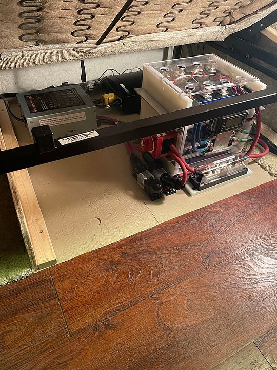
I set both controllers to the same parameters, set the portables out in the sun. Interesting - they are poly panels, 160W total, were outputting 8A in boost mode. The 430W roof panels are flat, they were putting out 12A, boost mode. Obviously orientation to the sun is critical for best performance.

Both appear to work exactly as expected. Both charged at full current for a couple of hours until the pack reached about 13.5V, then the smaller controller dropped to float. The larger one stayed in boost for quite awhile longer. I tried changing the boost duration but that didn't change anything. The pack had to reach a certain level, and then the controller dropped to float. This happened at right about 92-93% of full SOC. At float both controller reduced current by about half, and continued to peak the pack up to 100% SOC.

As mentioned previously, if charge voltage is set higher than 3.5V per cell, when all of the cells reach that level there are two of the four that will start to accelerate past the other two. Setting the float over 13.4 results in the cells becoming out of balance at charge termination. This tells me the top balance isn't perfect, one cell is reaching full charge before the others.

Charging the pack to 99% keeps them all in balance - going over results in imbalance. If I leave the charge voltage high, such as with the powermax, one cell goes over voltage and bms shuts off charging. If I set CV at 13.4V current stops and the cells remain balanced.

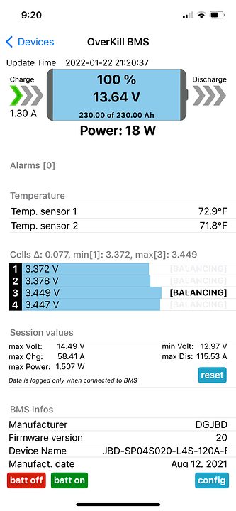
Here's charge state at the end of solar charging yesterday, current finally reached zero. I have a slight cell imbalance at this level:


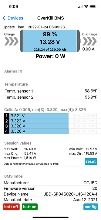
And this morning after resting:


Doing some more research I found I can either live with 99% charge level with lower charge voltage settings, or disassemble and do another top balance. Or do a few cycles and see if they come in to better balance at the top with BMS balancing.
 
Last edited:
@smoothJoey - will you look at these charge controller settings and tell me if they need to be changed, or if I have an out of balance problem?

At the top of the charge, when all cells are reaching full charge, there's at least one run-away, possibly two. They go into balance but the duration isn't long enough - should that be extended, possibly at a lower boost voltage? Or is this just because the cells are fully charged and the voltage is spiking up?

I could boost charge to 14.0 and float 13.4 and likely not get an out of balance on the cells. Is that also appropriate?
 
Could be a balance issue. You did the top balance, yes? Could also be an issue with the two cells such as different capacity or different internal resistance.

Charging to 13.8 on a daily basis is fine. I would keep your notes and run it. Take some additional notes each 30 to 60 days and see what goes. Not much you can really do.

While in use if you get the battery low on charge take notes what cells drop faster than the others as you get below 12 volts.

Normal for any differences to only show near the top or near the bottom. The voltage curve is so flat in the middle that no differences are shown.
 
Yes, top balanced the four cells to 3.65 perfectly , then assembled the pack.
They stay in sync until any of them go over 3.5 and then the delta starts to spread out. Left to rest and they all sync perfectly.

So I gather either try to re-balance them, disassemble and do a top balance, clean terminals and re-assemble. Or limit charge voltage to anything under 14.1. There's no way this pack will charge to 14.4 or 14.6 - one cell, #4, will hit the over-voltage on the bms and it shuts down charging.

It's not till the very top that the ones that reach full charge first shoot up in voltage. And the ones lagging are starting to discharge already. Balance on top just isn't happening. The bms will say it's balancing for a bit at 13.8, then the current drops off to nothing and the laggers start to drop back to resting voltage while the runner stays way up in voltage.

Here is a perfect example - and this will happen at 13.8 and anything over. Left to rest and they all settle to the same voltage.


If you can hold the voltage at 14.0 and at the same time boost charge one of the low cells and see if it stays in sync.
If it holds up, boost the other low cell.

Seems like a PITN to disassemble, top it again, and reassemble.
 

diy solar

diy solar
Back
Top