diy solar

diy solar

New system - seeking feedback on layout & install

ghoti

New Member
Joined
Dec 24, 2022
Messages
9
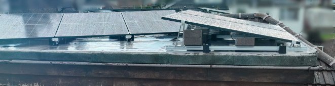
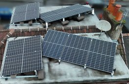
I attach photos of a recent solar install. I would be very grateful for comments -- and possible suggestions for suggested optimisations -- on the panel placement and workmanship.

Location is Scotland (latitude 56 degrees).

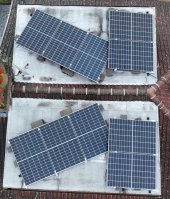
Concerning orientation: in the photo "above.jpeg", North-to-South is left-to-right.

Numbering the panels 1 (northeast / top-left in the photo "above.jpeg"), 2 (northwest / bottom-left), 3 (southeast / top-right), 4 (southwest / bottom-right), as per sunshine_eggo's response, the panels are on two parallel string inverters with numbers 1 and 3 in series, and 2 and 4 in series (by my understanding).

Thanks in advance.
 

Attachments

  • side.jpeg
    side.jpeg
    248.3 KB · Views: 15
  • top 1.jpeg
    top 1.jpeg
    287.2 KB · Views: 15
  • above.jpeg
    above.jpeg
    178.6 KB · Views: 14
Last edited:
As soon as the 2 panel array shades a single cell of the panel below it (3 shading 1 and 4 shading 2), it takes out the entire section I've outlined in red, i.e., 1/3 of half of that panel will no longer contribute anything.

1672438396058.png

If these are on microinverters, disregard the following. If on string inverters or MPPT charge controlers:

Given their perceived orientations, the following are valid combinations:
3 in series with 4
3 in parallel with 4
1 in parallel with 2
Each group on its own MPPT input.

If you put 1 (or 2) in series with 2 (or 1) or 3 or 4, the lower performing array will force the higher performing array to operate at reduced current and penalize performance.

Concerning workmanship, I can only hope the concrete blocks are not actually being used to hold the arrays down and that they are somehow securely fastened to the building structure.
 
As soon as the 2 panel array shades a single cell of the panel below it (3 shading 1 and 4 shading 2), it takes out the entire section I've outlined in red, i.e., 1/3 of half of that panel will no longer contribute anything.

View attachment 127068

If these are on microinverters, disregard the following. If on string inverters or MPPT charge controlers:

Given their perceived orientations, the following are valid combinations:
3 in series with 4
3 in parallel with 4
1 in parallel with 2
Each group on its own MPPT input.

If you put 1 (or 2) in series with 2 (or 1) or 3 or 4, the lower performing array will force the higher performing array to operate at reduced current and penalize performance.

Concerning workmanship, I can only hope the concrete blocks are not actually being used to hold the arrays down and that they are somehow securely fastened to the building structure.
Many thanks @sunshine_eggo. I have edited the post to provide additional information in the light of your response. 1&3 are in series and 2&4 are in series, in two parallel groups.

The concrete blocks are holding the arrays down; there is no connection to the building's structure, aside from weight. I am informed that this is standard practice for a flat roof.
 
Many thanks @sunshine_eggo. I have edited the post to provide additional information in the light of your response. 1&3 are in series and 2&4 are in series, in two parallel groups.

#1 and #3 (and #2 and #4) will throttle one another. Whichever one is getting better sun, it will be limited by the current produced by the array with worse sun.

#3 and #4 in series on one MPPT would maximize #3 and #4

#1 and #2 in parallel on the other MPPT would ensure they don't have an adverse impact on one another provided your MPPT can handle 2X the Imp of the panels.

The concrete blocks are holding the arrays down; there is no connection to the building's structure, aside from weight. I am informed that this is standard practice for a flat roof.

I can't imagine that is actually compliant to any code regardless of "standard practice," but I guess there could be exceptions for certain types of structures.
 
Why do 1 and 2 have a different azimuth than 3 and 4? It looks to me like you could've had simple parallel rows with no shading.
Thanks for the question.

The spec was for them all to be facing due South -- with no overlap. However, the contractor purchased mountings that did not fit the roof space, and rotated the northern pieces so they would fit. I questioned this and was told it would be only a few degrees rotation, but now having got these photos it's obviously much more than that (about 60 degrees off South, judging by eye).

Of course I know the rotation and overlap are not optimal, but I welcome input on whether this is a substantive issue.

(The arrays are in two parallel groups of 5 panels; 1&3 and 2&4.)
 
#1 and #3 (and #2 and #4) will throttle one another. Whichever one is getting better sun, it will be limited by the current produced by the array with worse sun.

#3 and #4 in series on one MPPT would maximize #3 and #4

#1 and #2 in parallel on the other MPPT would ensure they don't have an adverse impact on one another provided your MPPT can handle 2X the Imp of the panels.


I can't imagine that is actually compliant to any code regardless of "standard practice," but I guess there could be exceptions for certain types of structures.
Thank you. A question about your comment here:

"#1 and #3 (and #2 and #4) will throttle one another. Whichever one is getting better sun, it will be limited by the current produced by the array with worse sun."

So #1 and #3 are in series on a single string, by my understanding. #1 has three 400w panels, and #3 has two 400w panels. Does this mean that the combination of #1 and 3 in series will only produce as much as four panels, because #3 (with only two panels) will tend to throttle #1 (with three panels)?

Or is this purely about sun? That is, because subarray #1 points in a different direction than subarray #3, the array consisting of #1+#3 in series will always only produce as much current as the *less* illuminated sub-array?
 
Last edited:
Thanks for the question.

The spec was for them all to be facing due South -- with no overlap. However, the contractor purchased mountings that did not fit the roof space, and rotated the northern pieces so they would fit. I questioned this and was told it would be only a few degrees rotation, but now having got these photos it's obviously much more than that (about 60 degrees off South, judging by eye).

Of course I know the rotation and overlap are not optimal, but I welcome input on whether this is a substantive issue.

It is.

(The arrays are in two parallel groups of 5 panels; 1&3 and 2&4.)

Your contractor is a jackass. You did not get what you paid for. You have been overcharged, and they have underdelivered.

Given your northern latitude, I expect that much more of 1 and 2 are shaded by the south facing panels due to angle of the sun, so it's worse than what a straight down shot would imply. I'm 99% certain that the shaded panel will ALWAYS produce at most 5/6th of rated power in perfect conditions due to the shading.

Please note the following:

1672445123155.png

Your split cell panels are divided into sixths. I've outlined 3 of the 6 sections. The same 3 sections exist on the other half of the panel. If even a single cell is shaded in those sections, the entire section performs as that one cell does. As you can see 1/6th is always shaded, and given the current position of the sun and your Northern latitude, I expect the 2nd outlined section may be shaded as well as the closest one I didnt' outline... potentially compromising the performance of half of that panel.

You will NEVER get anything near your array's rated power even if you weren't in sunless Scotland.

Thank you. A question about your comment here:

"#1 and #3 (and #2 and #4) will throttle one another. Whichever one is getting better sun, it will be limited by the current produced by the array with worse sun."

So #1 and #3 are in series on a single string, by my understanding. #1 has three 400w panels, and #3 has two 400w panels. Does this mean that the combination of #1 and 3 in series will only produce as much as four panels, because #3 (with only two panels) will tend to throttle #1 (with three panels)?
Or is this purely about sun? That is, because subarray #1 points in a different direction than subarray #3, the array consisting of #1+#3 in series will always only produce as much current as the *less* illuminated sub-array?

It's about sun. Bottom line:

Short version: All panels in a string must face the same direction, or the ones facing more away from the sun will force the panels facing more towards the sun to perform as though they were at the less optimal facing.

A panel perfectly perpendicular to the sun at high noon directly overhead will have maximum output. This max output will be in the form of current. Let's say 10 Amps.

A panel in any condition that's less than perfect as described above will output less current. Let's say they are only outputting 60% or 6A.

If they are in series, all panels MUST pass the same amount of current. This will ALWAYS be the lower number, so the panels that could operate at 10A will only output 6A when wired in series with panels outputting 6A. Thus, you have lost 40% of your potential power from the two panels.
 
It is very significant. The panels provide power per Volts x Amps. If any cell is shaded, then it is no longer providing Amps, and can actually lose power as it gets heated by the other cells. Sunshine_eggo is absolutely right, that the shading from the upper panels will make the situation much worse than it looks from overhead. I would redo it or hire a new installer to come out and fix it. Who knows what other shortcuts he took? Loose connectors and bad connections will cause fires.
 
It is.


Your contractor is a jackass. You did not get what you paid for. You have been overcharged, and they have underdelivered.

Given your northern latitude, I expect that much more of 1 and 2 are shaded by the south facing panels due to angle of the sun, so it's worse than what a straight down shot would imply. I'm 99% certain that the shaded panel will ALWAYS produce at most 5/6th of rated power in perfect conditions due to the shading.

Please note the following:

View attachment 127085

Your split cell panels are divided into sixths. I've outlined 3 of the 6 sections. The same 3 sections exist on the other half of the panel. If even a single cell is shaded in those sections, the entire section performs as that one cell does. As you can see 1/6th is always shaded, and given the current position of the sun and your Northern latitude, I expect the 2nd outlined section may be shaded as well as the closest one I didnt' outline... potentially compromising the performance of half of that panel.

You will NEVER get anything near your array's rated power even if you weren't in sunless Scotland.


It's about sun. Bottom line:

Short version: All panels in a string must face the same direction, or the ones facing more away from the sun will force the panels facing more towards the sun to perform as though they were at the less optimal facing.

A panel perfectly perpendicular to the sun at high noon directly overhead will have maximum output. This max output will be in the form of current. Let's say 10 Amps.

A panel in any condition that's less than perfect as described above will output less current. Let's say they are only outputting 60% or 6A.

If they are in series, all panels MUST pass the same amount of current. This will ALWAYS be the lower number, so the panels that could operate at 10A will only output 6A when wired in series with panels outputting 6A. Thus, you have lost 40% of your potential power from the two panels.
Thanks for this detailed reply. I agree that the section you highlight here will always be in shade. Please let me be sure that I understand the full import of this information.

Let's suppose it's noon on a sunny day -- a best-case scenario for an unshaded solar install facing south, as per the original spec.

Suppose that the panel you highlight is 50% illuminated due to shading (a simplistic but reasonable approximation).
Do I understand correctly that this would throttle the entire array of five panels (1&3) to 50%?

Furthermore, sub-array 1 faces south-east, and sub-array 3 faces south. Thus, the half-illuminated panel in SE-facing sub-array 1 is anyway getting half as much sun per unit area as the panels in S-facing sub-array 3 (because cos(60)=0.5). Thus, the effective throttling on sub-array 3 is 75%.

Put another way: subject to these assumptions, this install would operate at around 25% of the capacity originally projected -- essentially, because it's bottlenecked by a single panel that's rotated and shaded.

Have I understood the overall problem correctly, even if the precise numbers may vary?
 
Thanks for this detailed reply. I agree that the section you highlight here will always be in shade. Please let me be sure that I understand the full import of this information.

Let's suppose it's noon on a sunny day -- a best-case scenario for an unshaded solar install facing south, as per the original spec.

Suppose that the panel you highlight is 50% illuminated due to shading (a simplistic but reasonable approximation).
Do I understand correctly that this would throttle the entire array of five panels (1&3) to 50%?

The shading will inhibit that panel. It won't force the entire array to 50%. Array #1 will produce no more than 5/6th of what it would produce if not shaded. 5/6 of the array will output the unshaded current, but it will lose the voltage from 1/2 of the shaded panel. The loss of voltage is what results in lost power.

Furthermore, sub-array 1 faces south-east, and sub-array 3 faces south. Thus, the half-illuminated panel in SE-facing sub-array 1 is anyway getting half as much sun per unit area as the panels in S-facing sub-array 3 (because cos(60)=0.5). Thus, the effective throttling on sub-array 3 is 75%.

They aren't going to compound each other. The SE array will perform like an SE array with half of one of its panels missing. The S array will be forced to operate at the lower current of the SE array.

Example:
Assuming 400W panels operating at 40V and 10A STC rating.
SE Array operates at 60% of the current of the S Array, so 6A, 40V * 3 = 720W
Shading cuts 1/6 of this power due to voltage drop, so 5/6 * 720W = 600W
S array operates at 100%, so 10A, 40V * 2 = 800W
However, the SE array will force a maximum of 6A from the S array, so 6A * 40V * 2 = 480W

Thus SE gives you 600W vs. 720W due to shading AND orientation
Thus S gives you 480W vs. 800W due to current restriction from orientation of SE array.

Yielding a total of:
1. 1080W vs. 2000W rated, 54% of rated.
2. 1080W vs. 720+800W = 1520W if UNSHADED and in different strings, 76% of rated
3. 1080W vs. 600W+800W = 1400W if SHADED and in different strings, 70% of rated

As you can see, the shading has far less impact than the different orientations of the panels.

Simply stringing 3 and 4 together in series and 1 and 2 together in parallel would greatly improve your potential output.

Put another way: subject to these assumptions, this install would operate at around 25% of the capacity originally projected -- essentially, because it's bottlenecked by a single panel that's rotated and shaded.

Have I understood the overall problem correctly, even if the precise numbers may vary?

Not entirely. Hopefully, I've clarified above.
 
Back
Top