Needing any and all advice as if any changes need to be made to my ANT BMS for safe operation. I'm very new to the solar world and wanting to make sure i have my BMS set to SMART and SAFE values.
Battery Bank - 3.2V 200AH Lifepo4 Prismatic Cells 48V
ANT Smart 300A BMS
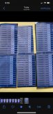
Parameters:
see attachment
Thanks for any and all suggestions.
Battery Bank - 3.2V 200AH Lifepo4 Prismatic Cells 48V
ANT Smart 300A BMS
Parameters:
see attachment
Thanks for any and all suggestions.