diy solar

diy solar

Newbie need advice with charging batteries using solar charge controller

Kahavia

New Member
Joined
Feb 1, 2022
Messages
8
Hi,

If my question has been posted in the wrong forum I apologize.

My system:
Off grid home system with 3 50W solar panels in parallell, 1 EPEVER MPPT Triron 2210N charge controller, 2 80Ah flooded lead acid batteries in parallell and 1 1000W inverter (in going current reduced by 40A fuse). Charge controller and inverter are connected to the batteries: plus on one battery and minus on the other. The battery settings on the charge controller is flooded and 80Ah, as it should be.

Today I connected my off grid solar system and though it is winter and low sun were I live in Sweden it seem to work but there is one thing that bothers me. All equipment is brand new but the batteries was not fully charged when I got them so I charged them with my regular 12V charger until they where fully charged according to the LED indicator on the charger. Now they both have 13.05V. When connected to the charge controller it says that they only have about 70% capacity! If I disconnect all cables and reconnect only the charge controller to one battery at the time it says the same thing: 70%. What is going on?

Is there something I've missed or is either the batteries, the regular charger or the charge controller malfunctioning?

Best regards
Kahavia
The 40A fuse won't reduce in going current, it will just burn if you exceed 500W-600W load on the inverter.
The charge controller may be setup for a battery that has 13.05V at 70% SOC.
 
The 40A fuse won't reduce in going current, it will just burn if you exceed 500W-600W load on the inverter.
You are right of course. My initial idea was to limit the load on the batteries if some family member tried to use the inverter to its full capacity and drain the batteries.

The charge controller may be setup for a battery that has 13.05V at 70% SOC.
Forgive a newbie, does that mean that if I continue to charge the batteries with my CC the voltage and charge level will still increase?
 
the voltage and charge level will still increase?
That would be the expected results
2 80Ah flooded lead acid batteries in parallell
You should select 160Ah as the battery load not 80Ah
and 1 1000W inverter (in going current reduced by 40A fuse).
initial idea was to limit the load on the batteries if some family member tried to use the inverter to its full capacity and drain the batteries.
The 1000W inverter will still drain the batteries with a 40A fuse if the batteries are run extensively for a long period at 3A 12V but the fuse will blow if you use over ~8 Amps at 120V
You need adequately sized cables for a 80A 12V load and probably a 100A fuse. (I’d personally use 2/0 and fuse at 100A)
 
Last edited:
Battery voltage is not a good reference for state of charge (SOC). Your charge controller thinks 13.5 volts is about 70% capacity.
If you get some good solar gain and the controller in boost/absorb charge mode, you should see the pack come up to about 14.3V or so and then it will show it as 100% SOC. Does not mean sufficient amps have been supplied to the pack to fully charge it, and why there's an absorption stage where current is fed in at a constant voltage to fully charge the batteries. They will accept less and less as they reach full SOC.

The only way to accurately measure charge level is with a shunt and something to measure amps in and amps out. You calibrate it at full or empty, then your meter counts amps and tells you how much you have left, or how much you've taken out. Lead acid batteries do tend to sag quite a bit under load, and depending on your connect wire gauge you may be getting more drop than you want as well, which just serves to draw more amps to keep up with the inverter output.

The fuse on your inverter isn't a good way to limit use. It should be sized to accommodate the wire size and load, so that if there is an over-current or short it doesn't overheat your wires. For a 1000W inverter, 12V draw could be up to 90-100A 12V, so your fuse should be 125% of the load, or a 125A fuse. But you also need wire to handle that amount of current. The installation manual for your inverter should cover all of those parameters for you.

The Xantrex 1000 manual says it should have #4 AWG wire to carry that much current, and a 150A fuse. ANL is appropriate here, but there are other options as well. For that much current I would not use clamping connections, but properly crimped battery cable ring terminals. Ideally your connect wires are less than 3' long. Longer runs require heavier wire to prevent voltage drop.

If you want to limit current draw you need to monitor what your users are plugging into it. Tell wifey, 'no hair driers'. :ROFLMAO:
 
Last edited:
That would be the expected results
Good to hear, thanks! Still wonder why my regular charger indicated that the batteries were fully charged though. Bad quality?
You should select 160Ah as the battery load not 80Ah
Yes, in fact I did. Typing error.
You need adequately sized cables for a 80A 12V load and probably a 100A fuse. (I’d personally use 2/0 and fuse at 100A)
I'm currently using 16mm2 (about AWG 5). For AWG 2 I need to change to 35 mm2 cables.

Thanks for the advice!
 
Battery voltage is not a good reference for state of charge (SOC). Your charge controller thinks 13.5 volts is about 70% capacity.
If you get some good solar gain and the controller in boost/absorb charge mode, you should see the pack come up to about 14.3V or so and then it will show it as 100% SOC. Does not mean sufficient amps have been supplied to the pack to fully charge it, and why there's an absorption stage where current is fed in at a constant voltage to fully charge the batteries. They will accept less and less as they reach full SOC.

They only way to accurately measure charge level is with a shunt and something to measure amps in and amps out. You calibrate it at full or empty, then your meter counts amps and tells you how much you have left, or how much you've taken out. Lead acid batteries do tend to sag quite a bit under load, and depending on your connect wire gauge you may be getting more drop than you want as well, which just serves to draw more amps to keep up with the inverter output.
I will reconnect everything tomorrow and see. The forecast says sunshine :cool:
In my ignorance I thought measuring battery charge was simple.

The fuse on your inverter isn't a good way to limit use. It should be sized to accommodate the wire size and load, so that if there is an over-current or short it doesn't overheat your wires. For a 1000W inverter, 12V draw could be up to 90-100A 12V, so your fuse should be 125% of the load, or a 125A fuse. But you also need wire to handle that amount of current. The installation manual for your inverter should cover all of those parameters for you. Xantrex 1000 manual says it should have #4 AWG wire to carry that much current, and a 150A fuse. ANL is appropriate here, but there are other options as well. For that much current I would not use clamping connections, but properly crimped battery cables. Ideally your connect wires are less than 3' long. Longer runs require heavier wire to prevent voltage drop.
There are no clamps and all cables are crimped and less than 3' so that seem ok but I need new cables and fuses on that side of the system then.
Strange thing: As I recall 16mm2 (AWG 5) was nearly the thickest cable I could use for the inverter. AWG 2 is 35mm2, twice as much.

If you want to limit current draw you need to monitor what your users are plugging into it. Tell wifey, 'no hair driers'. :ROFLMAO:
Spot on!
 
What is your inverter model?
The installation manual should tell you cabling and fusing sizes. I used Xantrex as an example - but they're all pretty similar if they're similar size/current rating.

By crimping I meant your cable ends to fuse holder posts - get a proper connect post ANL block and install ring lugs on your cables. I really like the Spartan Power ones, but others are good as well - Blue Sea, LittleFuse, Buss, etc.
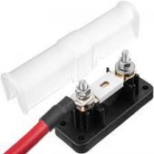
I had one like at the bottom here, and the wire after it would get warm - it was obviously high resistance. You can't get a good enough clamp on the wire. Fuse should be as close to the battery as possible. Another good option is a post fuse on the battery terminal.

My inverter is a 600w, 540 continuous, it's on 4awg cable with the big 80A fuse block, and the terminals get to 80*F - 30*C on full current. A thousand watt is even more, it's nearly double. It will also run your pack down very fast, at full load.


Like this:
1643758481762.jpeg

Not this:
images
 
Here is the manual for the inverter I have: https://www.kjell.com/globalassets/mediaassets/825703_44523_manual_en_no_sv.pdf?ref=79C7371BA0

The included cables were actually much thinner then those I'm using right now, just 10mm2 (AWG 8). On the other hand it does not look like copper cable. The manual mentions Fuse 25Ax5. Perhaps that means 125A? It's not clear to me if that's an internal fuse though.

I am using crimped ring lugs and I have a fuse box between inverter and batteries for AGU fuses up to 1080A. There are no ring lugs for the fuse box though.
 
Oh my, that’s not much of a manual.
Output is 230V?

I don’t know about an internal fuse.

The wire could be aluminum, or tinned copper.

6 or 8 gauge wire is a little light for 80-100A. At least 4, and 125-150A fuse.

Your charging should be okay. You will probably want more battery. :)
 
currently using 16mm2 (about AWG 5). For AWG 2 I need to change to 35 mm2 cables.
2ga is sufficient by ABYC chart.
You’re right: 2/0 is not required, just what I’d do. It lends possible efficiency plus headroom if you increase inverter capacity without needing to buy cables- again.
 
My charge controller says the battery is 100% when it reaches the absorption voltage setting.
My BMS says whatever amps are replaced to 100% is 100%.
Same for my smart meter - amps replaced to 100% is full charge.
 
Oh my, that’s not much of a manual.
Output is 230V?

I don’t know about an internal fuse.

The wire could be aluminum, or tinned copper.

6 or 8 gauge wire is a little light for 80-100A. At least 4, and 125-150A fuse.

Your charging should be okay. You will probably want more battery. :)
I ordered a new 500W (continuous 400W) inverter from Amazon.se. The intended top consumer for my system is just 300W and needed infrequently. Perhaps a bit radical but it gives me a better stomach feeling :)

Then, maybe, I only need to change the fuse between batteries and inverter and I'm good to go? And my two batteries will last a bit longer.

Hopefully I or someone else might have a need for the other inverter at some point.
 
Well, that's one way to fix connection issues - reduce current potential. (y)
The installation manual will have connection wire and fuse recommendations.

A smaller capacity inverter also has a lower standby consumption. I put a remote switch on mine so it's easy to initialize for use or turn off when not being used.
 
If you get some good solar gain and the controller in boost/absorb charge mode, you should see the pack come up to about 14.3V or so and then it will show it as 100% SOC. Does not mean sufficient amps have been supplied to the pack to fully charge it, and why there's an absorption stage where current is fed in at a constant voltage to fully charge the batteries.
Today was a sunny day and the batteries were charged to 100% already at 1pm. Voltage about 14,4. At sunset it sunk back to 13V and about 69%. All according to the controller. No load on the batteries except perhaps the controller itself, inverter disconnected. Normal?

remote switch
Good idea!
 
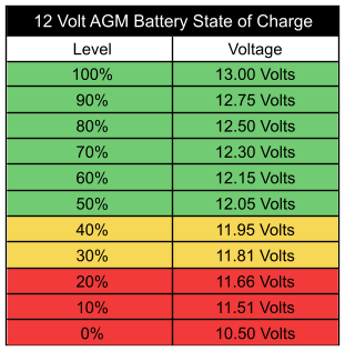
Yes, seems normal. AGM at 100% should rest at about 12.7-12.8V after 12-24 hours with no load. And why the SCC is not a good indicator of state of charge. Tail current, as they call it - the amount of current at the end of charge, is a better indicator. It would be down to near zero as the battery reaches full charge. But you have to catch it before the controller switches to float, which is a lower resting voltage, and charge termination. Default float is for AGM usually around 13.2-13.4. Absorption stage is generally about 14.4 for AGM. Flooded lead-acid is a little higher, 14.6-14.8.

893139_SoC_Table.jpg


And if you search around enough you'll find this one too. In any case, you're at full charge for AGM.
You really shouldn't discharge below 50% at any kind of frequency for longer battery life. Discharging 80% frequently cuts life by about half.


state-of-charge-chart-for-agm-battery.png
 
Last edited:
My batteries are flooded lead-acid and when you mentioned it I remember seeing the voltage reach 14,6 occasionally.

We did have some snow during the night and I guess It took a little time for the sun to melt that (I didn't check before lunchtime). Also days are short here wintertime.

I expect to have full use from the system during Mars to October. Beginning of February, not so much, unless I add more panels.
 
Sorry, I thought I read AGM. FLA likes to be cooked regularly, burns off the sulfated plates. I actually prefer them over AGM, which I think are over-priced unless you have a specific need for mounting and stability - like a race boat, 4X4, etc. At least with FLA you can ensure the electrolyte level is maintained - of course you have to look at them regularly. LOL I lived with a pair of golf-cart 6V in series for house batteries in the RV over the past 20 years. Always worked well for us. Just not much capacity. I just built a 230A lifepo4 pack with the help from forum members here. It's great.

12.7 is definitely resting voltage for lead acid. Your SCC will show well down SOC at that voltage.

I hate to recommend such a cheap meter, but hey, for $25 or $40 or whatever they are, I really like mine. Has a super cool BT app as well. Sure, a Victron is the gold-standard, but about ten times the cost.
A shunt meter will keep track of amps in and amps out.
My install and test post is #72:
 
Back
Top