diy solar

diy solar

Next Step, DVCC

gcap

New Member
Joined
Nov 6, 2022
Messages
16
I’ve recently completed the first steps of my first system ( see signature ) and have been getting familiar with the settings in the last few weeks.( I remove AC-IN for a bit then re-plug it to charge the batts )

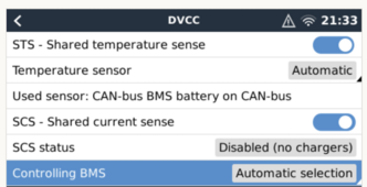
It has been suggested that I enable DVCC for more accurate measurements so a few days ago I connected it up but not sure about the settings and if I should trust it will do everything it is supposed to given I’m not using Victron supported batteries. The compatibility document clearly states problems can arise with untested batteries. Given they are untested, I don’t really know what settings to activate so I have turned on all the settings so that it hands as much info possible over to the Cerbo.

Thanks in advance,


SETTINGS
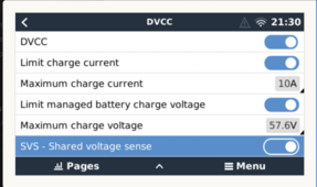
Screenshot 2024-02-25 at 9.30.38 PM.pngScreenshot 2024-02-25 at 9.33.21 PM.png

INFO FROM BATTERIES

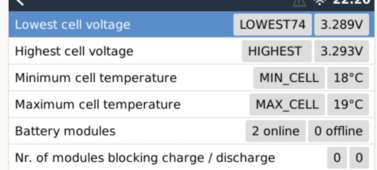
Screenshot 2024-02-25 at 10.18.32 PM.pngScreenshot 2024-02-25 at 10.20.50 PM.png

How can I know that it’s working properly?
What should I be looking out for to catch a charge or discharge gone wrong?
Also, am I correct in thinking that some of the shunts settings are irrelevant with dvcc active?
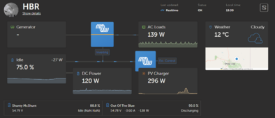
Since activating DVCC the shunt display shows NaN:NaN, anyone know why?
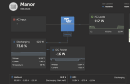

Screenshot 2024-02-25 at 12.44.48 PM.png
 
Last edited:
In your case (and mine) when the battery’s bms is not tied to the Cerbo, then the shunt is extremely important.

DVCC will pass current and voltage to all charging items: mppt’s, Multiplus, anything else that’s connected and temp data too.

You can set a max charge, that way, I only get 100a charging - not 120a form Multiplus, plus 50a from mppt#1 and 30a from mppt#2 for a possible 200a of charge.
 
Hi, when you say "BMS not tied to the Cerbo" what do you mean?
 
Ok - you added additional info…Your batteries are tied to your Cerbo…

Unfortunately, because I have never tied my batteries to thdd we Cerbo (via the CAN-Bus), I will not be of much help.
 
Ok - you added additional info…Your batteries are tied to your Cerbo…

Unfortunately, because I have never tied my batteries to thdd we Cerbo (via the CAN-Bus), I will not be of much help.
Sorry about that, yes, I added the photos to clarify what I'm seeing.

I still have my doubts about it functioning properly though. I guess it's the kind of thing you have to have at least seen working properly once to know whether it's supposed to look a certain way, or to know if something's missing.

Also, after painstakingly going back and forth with kind forum community members for help in understanding and analyzing all sorts of data to get to a place you're comfortable with just to hand over control to a BMS that you don't know will work or not.
 
I have a Batrium in control of the Cerbo.

When the Victron shunt is not the primary battery monitor, it's common to display NaN:NaN. That's the time to go value, i.e., when you set your shunt discharge floor in VictronConnect, the shunt calculates the time remaining time to that SoC level. That value appears here. My BMV-702 does the same. You should still see the value in VC.

It's something I don't care about, so I haven't pursued it. It still appears in VC if I care.

1708986668936.png
 
Be very very certain about the Shared Voltage Sense setting.

If it is on, and the BMS has disconnected the batteries for overvoltage, the voltage that the BMS shares may be the internal battery voltage
and not the outside. I had a situation where the external voltage got all the way to 61V. The BMS was protecting the batteries, but I was freaking out. Turning off shared voltage sense was correct for my batteries. I also have a shunt, so I was able to log this runaway voltage.

I do everything open loop now, I do not fully trust the BMS to do the right thing (for other reasons).
Thus, my batteries are no longer “tied to my Cerbo GX”.

Finally... an explanation for why the Pylontech protocol FORCES SVS off.

Thanks.
 
OK, thanks all, there's a lot of info to get into here.

Is a Batrium an external bms or SmartER Shunt?
With regard to the "time to go" does the smarthsunt tell the Cerbo what discharge % I've entered? If so, given my battery and shunt are showing different states of charge and both are displayed in the remote console, which one is used?

So given I have no experience with this bms, it seems that SVS should be off, I'll go that safe route but then you say
"Thus, my batteries are no longer “tied to my Cerbo GX”", the other functions of DVCC are still active and controlling are they not?

And as previously asked,
"How can I know that it’s working properly?
What should I be looking out for to catch a charge or discharge gone wrong?"

Thanks
 
OK, thanks all, there's a lot of info to get into here.

Is a Batrium an external bms or SmartER Shunt?

Yes. It's a high-end BMS with its own shunt. It has no means of disconnecting the battery. I must supply that myself via contactors. It also communicates with my equipment commanding the charger off or the inverter shut down if limits are hit. The BMS alone was $1000.

With regard to the "time to go" does the smarthsunt tell the Cerbo what discharge % I've entered?

No. The discharge floor exists only for the time to go calculation.

If so, given my battery and shunt are showing different states of charge and both are displayed in the remote console, which one is used?

You have three battery monitors:

1709082589521.png

So given I have no experience with this bms, it seems that SVS should be off, I'll go that safe route but then you say
"Thus, my batteries are no longer “tied to my Cerbo GX”",

No, its just that the battery voltage is not passed to all connected components and they rely on their own measurement, which may be influenced by current.

the other functions of DVCC are still active and controlling are they not?

Yes.

And as previously asked,
"How can I know that it’s working properly?

Test it. alter your BMS settings to where they will trip in normal operation and verify they are working.

What should I be looking out for to catch a charge or discharge gone wrong?"

Once you've tested it, you basically just have to trust it. Furthermore, you also program your chargers to stay within safe voltages.
 
Ok, I understand the Batrium,

I was sure the discharge floor % in the shunt told the multiplus to stop inverting , good to know. SO if I'm not around during a power failure and the MP doesn't stop inverting am I relying on the internal batt BMS to kick in?

You have three battery monitors: /
yes, obvious now. haha

Test it. alter your BMS settings to where they will trip in normal operation and verify they are working..

On the battery bms? My BMS only displays info, doesn't allow me to modify it.
Is the test setting to be modified in the victron settings? which?

Furthermore, you also program your chargers to stay within safe voltages.
After playing with the charger settings for a while I finally adjusted the settings at the victron default of 57.6 charge, 54 float and shunt charged V at 53.8
 
Ok, I understand the Batrium,

I was sure the discharge floor % in the shunt told the multiplus to stop inverting , good to know. SO if I'm not around during a power failure and the MP doesn't stop inverting am I relying on the internal batt BMS to kick in?

Nope. It has no function whatsoever other than to calculate the time. The MP has an internal setting to cut off below X volts. You can DL the config file, edit in VEconfig and then upload to reprogram.

You have three battery monitors: /
yes, obvious now. haha

Test it. alter your BMS settings to where they will trip in normal operation and verify they are working..

On the battery bms?

Yes.

My BMS only displays info, doesn't allow me to modify it.

Unfortunate.

Is the test setting to be modified in the victron settings? which?

Nope.

Furthermore, you also program your chargers to stay within safe voltages.
After playing with the charger settings for a while I finally adjusted the settings at the victron default of 57.6 charge, 54 float and shunt charged V at 53.8

I'd set the chargers to 55.2V - 3.45V/cell with a 1 hr fixed absorption time. These will only be used if the BMS stops controlling the system.

If you have solar, your charged voltage needs to be 0.2-0.3V below ABSORPTION. Intermittent solar can cause false sync to 100%.
 
DL the config file, edit in VEconfig and then upload to reprogram.
Yes of course, I'm still new to this so don't remember all the settings.
I remember setting it at 48V shutdown, 49V restart and 49.5V pre alarm.
These will only be used if the BMS stops controlling the system.
I'll reset the settings to your suggestions and will keep the solar mppt settings noted for when I get solar, soon I hope.
charged voltage needs to be 0.2-0.3V below ABSORPTION
As I don't have solar yet, will this be set in the mppt menu or a new menu will appear in the shunt? currently in the smarthsunt this is set .2 below float


Just now I was scrolling the many BMS menus to see if I could edit any, they all seemed to be in their normal/default state or 0’s. Alarm Status, Protect Status were all OK then I came across 3 settings with the following numbers under the "Failure Alarm" menu title,

Over Cur CNT: 2, OVER Chg CNT: 12 and Over Dchg CNT: 10 on battery 1
Over Cur CNT: 2, OVER Chg CNT: 13 and Over Dchg CNT: 7 on battery 2

The red alarm light on the front has never lit, the batteries have never gone lower than 20% charge, I've never pulled more than 140W from the inverter.
 
Last edited:
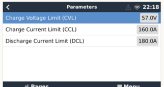
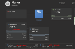
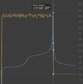
I tested my setup with a full charge and the updated settings to see how DVCC would do and all seems fine to me. I'm still not sure how the charge setting of ( 55.2V - 3.45V/cell ) interacts with the battery's setting of 57V sent to to the DVCC setting page.

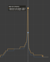
Does anything stand out from the following screenshots or just trust it and be done?


Screenshot 2024-02-29 at 11.14.56 AM.pngScreenshot 2024-02-29 at 11.01.35 AM.pngScreenshot 2024-02-29 at 11.06.02 AM.png
 
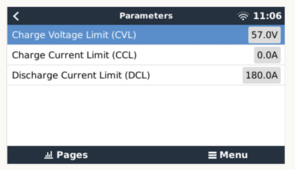
CVL: The BMS is telling the Cerbo never to give it more than 57.0V.

CCL: The BMS is telling the Cerbo to stop charging the battery (0A), it is full (as determined by the BMS SoC).
It doesn’t matter what the voltage is, when it says it is full, it is full.
If the batteries are well top-balanced, the voltage when this occurs will be higher.
If you are near 55.2V when it cuts off charging, most people on the forum think that is good enough.

Looks like your spread in cell voltages is from 3.46 to 3.58V when the CCL told the cerbo to stop charging.
I’d be very happy with that.

DCL: The BMS may disconnect the batteries if you draw more current than this.

If you followed @sunshine_eggo advice, you’ve made it so that even if the BMS connection fails, that the charging devices in your system will not overcharge your batteries.
 
Last edited:
battery's setting of 57V sent to to the DVCC setting page.

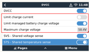
You can specify your own charge current and voltage limits:


1709232528945.png


These will override the BMS if they are more restrictive, e.g., with CVL set to 57V, if you put in 54V, 54V will be respected. If you put in 58V, it will be ignored, and the BMS will use its CVL.

My cells are NMC, so 58.4V is about 4.17V/cell, which is near the upper limit. I set this as I can easily change my BMS limits, and this is to protect me if I do something stupid... :)
 
CVL: The BMS is telling the Cerbo never to give it more than 57.0V.
I was interpreting it as the BMS asking for that voltage, not setting it as a limit.

These will override the BMS if they are more restrictive,
Now I get it, because I thought the BMS was asking for 57.0, I figured my setting of 55.2 was sort of moot, I was interpreting it backwards.

Thanks guys
 
Back
Top