diy solar

diy solar

Off Grid Cabin Design - Grounding Question

timgreb

New Member
Joined
Jul 11, 2022
Messages
3
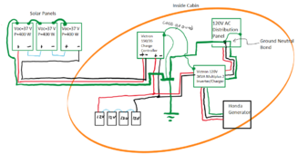
I am designing a 48V solar system for my off-grid cabin. I am using a Victron charge controller and Multiplus II.

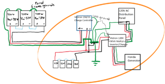
I have a question about grounding. I have looked at many resources but my head is spinning as it seems some of the information is inconsistent. I am hoping someone can set me on the right path.

My plan is to ground the solar panel frames to a grounding rod near the array [Grounding Rod #1]. I will NOT attach the solar array negative conductor to this grounding rod.

From the array, I will run positive and negative conductors(but not a ground wire) to the cabin. Inside the cabin, at the DC negative bus bar I will have a bond with a ground wire that will go to a grounding rod located at the cabin [Grounding Rod #2].

On the AC side, at the inverter output, I will bond the AC output ground to the DC negative bus bar above. I will also ground the metal frames of the charge controller and inverter to this ground.

Is this plan correct?
 
You will be told that your panel's frames should not have a separate ground rod from the house ground system. It used to be a common setup but now they want you to run a ground wire out to the panel's frame along with your (+) and (-). Your house ground may or may not need 2 ground rods wired in series and then to your cabin's distribution panel. From that it would be wired to all metal framework for electrical equipment.
 
Here is a diagram from a cabin design from a month or so ago - The end user was set on 24v made up of two 12v batteries in series and also on using a powerstrip for the output verse the direct wire lugs on his inverter. It met the OP in that thread's needs and may not meet your needs but it does explain how things connect and does include the ground wire. The solar cells are connected 2P2S

To add to what Matt says - you NEVER connect either positive or negative wire to the grounding system. You ONLY connect the equipment cases to that.


24v cabin.png


I also attached the drawio file so you can download drawio and make changes to it however you like.
 

Attachments

  • 24v cabin layout.drawio
    2 MB · Views: 2
Last edited:
Your responses are helpful. Please see diagram attached. I am assuming there will be a bond between ground and neutral in the AC distribution panel. I have not shown disconnects in the diagram for clarity. The green grounding symbol is meant to represent an appropriately sized grounding rod driven into the earth. Does the grounding portion of the diagram look correct? An important point that I am unsure of is whether I attach negative terminal of the battery to the system ground.
 

Attachments

  • GroundingDiagram.png
    GroundingDiagram.png
    345.3 KB · Views: 8
Your responses are helpful. Please see diagram attached. I am assuming there will be a bond between ground and neutral in the AC distribution panel. I have not shown disconnects in the diagram for clarity. The green grounding symbol is meant to represent an appropriately sized grounding rod driven into the earth. Does the grounding portion of the diagram look correct? An important point that I am unsure of is whether I attach negative terminal of the battery to the system ground.

Your set up is almost literally identical as mine (my CC is a victron 250/60). I have mine wired exactly as yours. (Except my N/G bond is in the inverter). It doesn’t have any grounding wiring yet (this weekend).

As for the battery negitive to ground… no one seems to do that on these forums. Filter guy has a nice series for download about grounding he talks about it.

Victron makes no mention of it in their manuals, HOWEVER Victron’s “wiring unlimited” clearly says to bond your dc system to ground at the battery, and also has illustrations showing such.

If you do, make sure the bond is after your battery bms.

From wiring unlimited:

IMG_7049.jpeg

My “system” so far:

IMG_1778.jpeg
 
Your responses are helpful. Please see diagram attached. I am assuming there will be a bond between ground and neutral in the AC distribution panel. I have not shown disconnects in the diagram for clarity. The green grounding symbol is meant to represent an appropriately sized grounding rod driven into the earth. Does the grounding portion of the diagram look correct? An important point that I am unsure of is whether I attach negative terminal of the battery to the system ground.

Were it grid tied you would do the N-G bond at the first point of entrance. Without a grid connected you can do the N-G in the main panel or in the inverter. My preference is to do it with a screw where you can see it and in the main panel where most would expect it. There can be only one N-G bond, there can be only one grounding system.

Your diagram looks right.

Note, in general the ground conductor is in sequence from one box to the next. It isn't typically run in a star spoke pattern

Used to be the negative pole of the battery was attached to the grounding system. It was clarified in the NEC and only the rack the battery is stored in gets grounded.
 
Last edited:
One other thing to consider (hopefully timselectric will stop by and clarify) but you may or may not have a ground loop

Filter guy says most inverters tie AC EGC to the case, BUT Victron says all their inverter/chargers isolate AC circuitry from the chassis. The exception is if your N/G bond is at the inverter, in which case the AC circuit does connect to chassis.

From filter guy:

IMG_7050.jpeg

From Victron wiring unlimited:

IMG_7051.jpeg
 
Were it grid tied you would do the N-G bond at the first point of entrance. Without a grid connected you can do the N-G in the main panel or in the inverter. My preference is to do it with a screw where you can see it and in the main panel where most would expect it. There can be only one N-G bond, there can be only one grounding system.

Your diagram looks right.

Used to be the negative pole of the battery was attached to the grounding system. It was clarified in the NEC and only the rack the battery is stored in gets grounded.

Battery rack would be the EGC. Victron says to bond DC negative to ground.
 
Not in the US. They are in the Netherlands and rules vary country to country.
 
Not in the US. They are in the Netherlands and rules vary country to country.

It’s in the nec. Optional but recommended. I,think grounding is grounding. Wiring unlimited covers grounding and bonding and it seems like it’s the same in the Netherlands.

Hopefully Tim will swing by to clarify
 
@timselectric , can you swing by and provide an answer

A little research -

### Quoting NEC 250.162
>250.162 Direct-Current Circuits.
>
> (A) Two-Wire, Direct-Current Systems. One conductor of a two-wire, direct-current system shall be grounded. Exception: A system equipped with a ground detector and supplying only industrial equipment in limited areas shall not be required to be grounded.
>
> (B) Three-Wire, Direct-Current Systems. The neutral conductor of a three-wire, direct-current system shall be grounded."

### Why It Is Common Practice to Not Ground the Negative Wire of a PV ESS

While NEC 250.162(A) states that one conductor of a two-wire DC system should be grounded, the practice of not grounding the negative wire of a photovoltaic (PV) energy storage system (ESS) has become more common for several reasons:

1. **Transformerless Inverters:**
- Modern PV systems often use transformerless inverters, which are more efficient but do not isolate the DC side from the AC side. In such systems, grounding the negative conductor can create ground loops or other issues, making it less desirable or even impractical.

2. **Safety and Arc Fault Protection:**
- Floating (ungrounded) systems can improve safety and arc fault protection. Grounded systems can create a single point of failure, which could result in dangerous ground faults. Floating systems can detect faults on both positive and negative conductors, providing better fault detection and safety.

3. **System Flexibility:**
- Ungrounded systems allow for more flexible system design and easier integration of different system components. This flexibility is particularly important in complex PV and ESS installations.

4. **Compliance with International Standards:**
- In some cases, international standards and practices influence design choices. Many European systems, for example, are designed to be ungrounded or floating. As global manufacturers design products for multiple markets, they often adopt these practices.

5. **Reduced Corrosion:**
- Ungrounded systems can help reduce corrosion issues, particularly in the case of certain battery chemistries and in environments where grounding can introduce unwanted electrochemical reactions.

### Practical Considerations

1. **Manufacturer Guidelines:**
- Always follow the manufacturer’s guidelines for grounding and bonding PV and ESS systems. These guidelines are tailored to the specific design and safety requirements of the products.

2. **System Configuration:**
- The decision to ground or not ground the negative conductor should be based on the specific configuration and safety requirements of the system. Factors include the type of inverter, the presence of a ground fault detector, and local code requirements.

3. **Local Codes:**
- Ensure compliance with local electrical codes and regulations. While the NEC provides a framework, local codes may have additional requirements or modifications that impact grounding practices.

### Conclusion

While NEC 250.162 requires grounding one conductor of a two-wire DC system, the practice of not grounding the negative wire of a PV ESS has become common due to modern inverter designs, safety considerations, system flexibility, international standards, and reduced corrosion concerns. Always refer to the latest NEC, manufacturer guidelines, and local codes when designing and installing PV and ESS systems.
 
Last edited:
:) My communications skills begin to drop as the day wanes.

See I just start to babble more as the day goes one. And my amount of babble is inversely proportionate to how much sense I am making.
 
In a mobile system (RV, camper, boat) the negative battery is bonded to the vehicle frame. The reason for this is because the vehicle starting system is already done this way. And the two systems (starting and house) are usually connected together at some point.

For a stationary system, it's better to keep the DC system isolated from ground.
So that ground detection devices can function properly.
Only ground the enclosures, frames, racking (exposed metal parts).

Victron is big in the mobile market. And I assume that this is why they still show DC bonding in their diagrams.
 
Wow, terrific information. Here is my latest iteration updated so that there is a single Neutral Ground bond in the system located in the Electrical Service Panel. If I understand correctly, there is a relay in the Multiplus 2 that I would disable so there is no bonding of Neutral and Ground within the Multiplus 2. In my latest diagram, I have colored the frames of each of the devices green so that it is clear that those frames are grounded.

I think that the neutral and ground conductors from the Honda generator are not bonded. They would get bonded in the service panel. In practice, I will not be connecting the generator to the system unless I need to charge the batteries due to insufficient solar production (multiple cloudy days in a row).

Let me know if I am missing something. I want to have the diagram correct for my own purposes but also in case it helps others.
 

Attachments

  • GroundingDiagram2.png
    GroundingDiagram2.png
    129.3 KB · Views: 3
In a mobile system (RV, camper, boat) the negative battery is bonded to the vehicle frame. The reason for this is because the vehicle starting system is already done this way. And the two systems (starting and house) are usually connected together at some point.

For a stationary system, it's better to keep the DC system isolated from ground.
So that ground detection devices can function properly.
Only ground the enclosures, frames, racking (exposed metal parts).

Victron is big in the mobile market. And I assume that this is why they still show DC bonding in their diagrams.
This is how I understand the grounding issue. The mobile inverters are bonded. I have kept my negative battery isolated from any grounding. I use the third wire for grounding. I treat PV wiring the same as AC. Not so much a positive and negative as more like two hot wires. On AC power, the ground wire starts where the bonding screw is. After that point it is completely isolated from the neutral.
 
Back
Top