diy solar

diy solar

Off-grid Solar / Battery monitoring and control freeware

Anyone tried to pull data from a Renogy 10A to an esp32 microcontroller? Would love some insight on how to actually connect the RS232 to it.
 
It's exactly the same as connecting a raspberry Pi or PC. Look at the thread for details.
I want to try and use the GPIO pins instead of connecting through usb. Was thinking about trying this out:

Also - would the script for pulling the data need to be modified a lot?
 
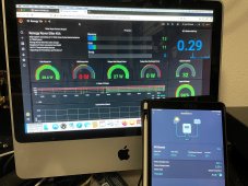
Wow what a learning curve! So after 3 days of fumbling through the cheat sheet, googling things and reading around the topic, I was able to successfully install Grafana, node exporter and prometheus. All successfully run on restart and I'm consistently getting system metrics in Grafana.
I feel like I've learnt a lot and am able to make my way around the console somewhat well now.

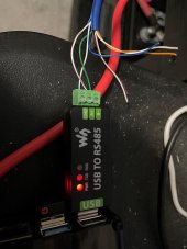
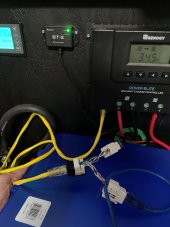
However I'm now having an issue getting data from the Chargery 16s BMS. I'm using COM3 port of the BMS. A red and black wire come out. They read 5v between them. Then the connection is to a RS232: Red->Green(TXD) and Black->Black (GND) and then to USB. I'm using the connector Joe suggested in his guide. Ive also tried Red->White (RXD), but also gotten no reply.
1646648033630.png

The python script getChargeryData.py runs, is aimed at the correct USB port, but I'm not getting any data into Grafana, nor into the ramdisk file.
When I cat the ramdisk file, it is completely empty.
I'm not sure whether the problem now is with the python script, or the data feed into the USB?
This is the output when I run dmesg when the script is running;
1646648254686.png
Can anyone with some coding insight please help? How can I test if there are signals coming from the USB port at all?

Thank you
 
Last edited:
[sudo] cat /dev/ttyUSB0 should give you an idea.
[sudo] meaning, if you get "permission denied" sort of things, use sudo or go root.
-
Thanks Don.
So there is nothing when I cat USB0. Which I presume means there is no data incoming at all from the USB...
Time to do some research on interfacing between the two.
 
Haven't read the whole thread, but I can give some advice. I've been running an RPI for multiple years (DIY surveillance system, CPU was constantly loaded at 80+ percent) and the main issue I had was with file system corruption. A few things that can be used to make the system more resilient are:

1) Power it from a non-interruptable power supply. If you have batteries for the system use them with a step-down converter to get 5.1 volts.
2) Keep the RPI with passive cooling and make sure it has sufficient ventilation holes.
3) Use read-only root FS with a memory overlay. The goal is to reduce to zero the sites to the root FS. This had the biggest impact on the reliability of my system. From 30-60 days without failures, I got to over a year with this single change.
4) Keep your data on secondary storage. The SD card used to store the root FS is not reliable for services like databases (i.e. InfluxDB) due to the common write operations. One option is to have a high-quality USB flash drive. Another option (better one) is to have a USB-powered external hard drive (HDD or SSD). This will fully offload the SD card from the read and write operations. On that storage keep both the data and the configurations.
4) Make regular backups on a remote storage. I had daily, weekly and monthly backups of second storage. I was keeping the last 5 of each type on a remote location. This way I had options to restore to the most recent unimpacted data in case of failures. All was accomplished by shell scripts with CRON scheduling.
5) Once the system is fully configured and you don't expect more changes on the root FS create a backup of the SD card. This would be both the way to share the system with other folks and to restore it in case of failure. Consider what passwords are stored on the root FS when sharing the image.

Be prepared for failures. These will happen. The higher the load is, the more often you'll experience them.

Mine RPI was also an access point equipped with a 4G stick. I managed to tunnel a few ports to a router with a static IP address and this way I managed to expose the whole system to the internet. Since it was a remote surveillance system I needed both ways to manage it and to disable it. SSH access accomplished the first, simple Python 2 Flask server accomplished the second.
 
This is my connection between the COM3 port on the Chargery BMS and the Raspberry pi Zero;
I've tried connecting red to white (RXD) aswell, to no avail. I am afraid to try other combinations incase the voltage destroys sensitive electronics.
Can anyone confirm what the right pin-out connection should be? This is a RS232 adapter sold on amazon, linked by Joe in his guide
(https://www.amazon.com/gp/product/B07554Z4LX/ref=ppx_yo_dt_b_asin_title_o02_s01?ie=UTF8&psc=1)
1646653217269.png
 
I want to try and use the GPIO pins instead of connecting through usb. Was thinking about trying this out:

Also - would the script for pulling the data need to be modified a lot?
You don't need that adaptor, the USB port on the PI4 is simply used as a virtual serial port.
You can connect the 3 wires from the solar charger directly to the GPIO pins exactly as you would fit any project using serial read, write and ground.
 
This is my connection between the COM3 port on the Chargery BMS and the Raspberry pi Zero;
I've tried connecting red to white (RXD) aswell, to no avail. I am afraid to try other combinations incase the voltage destroys sensitive electronics.
Can anyone confirm what the right pin-out connection should be? This is a RS232 adapter sold on amazon, linked by Joe in his guide
(https://www.amazon.com/gp/product/B07554Z4LX/ref=ppx_yo_dt_b_asin_title_o02_s01?ie=UTF8&psc=1)
View attachment 86396
The problem is with those cheap cables, they simply don't work for rs232. I tried them as they were very low cost, and wasted many hours.

Go get a real RS232 cable from a respected vendor and all will work as you expect.


I like DTech products, they worked great. You use them in combination with a simple DB5 breakout adaptor to get to the pins.

 
Last edited:
The problem is with those cheap cables, they simply don't work for rs232. I tried them as they were very low cost, and wasted many hours.

Go get a real RS232 cable from a respected vendor and all will work as you expect.


I like DTech products, they worked great. You use them in combination with a simple DB5 breakout adaptor to get to the pins.

Thank you for the quick reply. I will go get something similar tomorrow.
Do you think this will do? I remember you mentioning something about TTL not being good for the chargery? Doesn't it operate on lower voltages though?

Also, you should change the cable recommendation in your github page, as that is where I bought the cheaper cable that does not work.
 
Great Project! I've got this working with a Renogy Rover Elite MPPT. I also hacked a "splitter" together so I can run the BT-2 module as well as the Pi.

I'm still playing around with the data I want to collect using the Renogy modbus documentation and the graph layouts but I'm getting there. I don't know if it's specific to me or the Rover elite, but my modbus address was 16. Took a bit of scanning and checking the wiring on my test adapter to find it.
 

Attachments

  • 1.jpg
    1.jpg
    261.1 KB · Views: 22
  • 3.jpg
    3.jpg
    131.2 KB · Views: 23
  • 4.jpg
    4.jpg
    131.4 KB · Views: 24
So I bought a the right connector. Soldered the red wire to pin 3 and the black to pin 5. Connected it all up. Still no data when I cat /dev/ttyUSB0.
Any ideas what I'm doing wrong? More specifically, can anyone who has got the chargery working, describe their exact rs232 pinout connections? Which pin did you plug the red into and which the black into? Photos would be great.

This is the connector I've bought:
1646713216866.png

This is the output of dmesg, and trying to read the empty USB output
1646713242339.png
 
Last edited:
The connection is 3 wires, look back thru the blog for an example, also check dmesg to confirm the connection to USB0 is working after you plug it in.
 
The connection is 3 wires, look back thru the blog for an example, also check dmesg to confirm the connection to USB0 is working after you plug it in.
I have looked thru the whole thread and also the github. I can't find a clear example of the chargery connection. Nor a picture.
One person mentions red to pin 3 and black to ground, which is what I've tried. Doesn't work.
There are only 2 wires coming out of com3.
Which port are you using from the chargery then to get three wires?
Nowhere can I find described how to properly make this connection.
I would really appreciate a clear explanation.
 
Last edited:
Look at this old thread
 
You don't need that adaptor, the USB port on the PI4 is simply used as a virtual serial port.
You can connect the 3 wires from the solar charger directly to the GPIO pins exactly as you would fit any project using serial read, write and ground.
So technically this could be done also for the rp4 right? Connecting the 3 cables directly to the GPIO pins I mean.
How would you go about getting the python script to work on the esp32?
 
Look at this old thread
Yes I've looked through that thread and every other that comes up on a search for chargery here.
All you say is "connect using a simple USB interface with just RX/TX ports". Now you're saying there's 3 wires? Which port are you using on the chargery?
Plugging Red into Tx and Black into GND does not work, as suggested by Craig in his Chargery Communication thread.
Above you say Use RX/TX, can you please elaborate on this?

There are 2 wires coming out of COM3 on the Chargery BMS main unit. A red wire and a black wire.
1. Which of the 9 serial pins do you connect the red wire to.
2. Which of the 9 serial pins do you connect the black wire to.

Would really appreaciate a direct answer to those two questions, thank you.
 
Last edited:
Back
Top