You are using an out of date browser. It may not display this or other websites correctly.
You should upgrade or use an alternative browser.
You should upgrade or use an alternative browser.
Off-grid Solar / Battery monitoring and control freeware
- Thread starter BarkingSpider
- Start date
shadowsteve
Solar Enthusiast
- Joined
- Feb 11, 2021
- Messages
- 265
Who's using Influxdb on their system? My db is >2gb and now won't compact. I have no CQ or RP setup.
Sanwizard
Solar Wizard
- Joined
- Feb 2, 2021
- Messages
- 2,715
This maybe useful:
 blog.devgenius.io

Save 90% Disk Space By Compacting Your InfluxDB
Speed up your queries and reduce storage requirement. How to monitor InfluxDB itself with Grafana.
 blog.devgenius.io
shadowsteve
Solar Enthusiast
- Joined
- Feb 11, 2021
- Messages
- 265
I read that one. All of the data reduction I've seen so far requires creating another set of data with less points which changes the Grafana charting when you want to zoom in/out.This maybe useful:

Save 90% Disk Space By Compacting Your InfluxDB
Speed up your queries and reduce storage requirement. How to monitor InfluxDB itself with Grafana.blog.devgenius.io
Just wondered what others have setup for their db's. I can't be the only one that has run into this issue as it's a standard influx problem on large db's.
Just wondered what others have setup for their db's. I can't be the only one that has run into this issue as it's a standard influx problem on large db's.
Prometheus tends to use a lot less space for the same metrics compared to Influx. I never really had an issue logging and monitoring on my Pi.
As an aside, this is my new monitoring unit, should be in operation in a few weeks (once I have time):
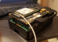
Consists of a RPi 3, a StromPi to provide the power directly from main battery voltage (so doesn't rely on an inverter for power) and a Sixfab LTE communication board. The device connects to my VPN server on startup, so I will be able to monitor everything from then on no matter where I am. The next step will be to add automation to make decisions based on weather conditions, state of charge, consumption patterns, etc. in an intelligent manner, probably with some machine learning or at least some statistical methods.
I now also have a script to read Ruuvi tags (temperature, humidity, etc.) to visualize in Grafana. I know there are other projects that do this, but they all rely on RuuviCollector, which is a rather heavy Java application and assumes Influx. Mine is much simpler, and follows the same idea as the other data extraction scripts talked about in the thread.

 github.com
GitHub - PurpleAlien/ruuvi_grafana: Read data from a RuuviTag and graph it in Grafana.
Read data from a RuuviTag and graph it in Grafana. - GitHub - PurpleAlien/ruuvi_grafana: Read data from a RuuviTag and graph it in Grafana.
I'm assembling this rig and will spin it up to attach to my MPP LV6548. I searched the thread and couldn't find any references to attaching a Daly BMS. I'm assuming it's fairly straight forward with plugging into the BMS uart but if anyone has any lessons learned, I'd like to hear.
Zapp Brannigan
New Member
- Joined
- Aug 29, 2022
- Messages
- 3
Did you install pymodbus?
or
Depending on your distro etc.
pip install pymodbusor
pip3 install pymodbusDepending on your distro etc.
Zapp Brannigan
New Member
- Joined
- Aug 29, 2022
- Messages
- 3
Did you install pymodbus?
pip install pymodbus
or
pip3 install pymodbus
Depending on your distro etc.
pip3 install -U pymodbusRemove the '.sync' bit from the import on line 33 in that getTracerData.py script and see if that works.
Zapp Brannigan
New Member
- Joined
- Aug 29, 2022
- Messages
- 3
Now i have this errorRemove the '.sync' bit from the import on line 33 in that getTracerData.py script and see if that works.
Traceback (most recent call last):
  File "/home/solar/SolarShed-master/getTracerData.py", line 35, in <module>
    from pyepsolartracer.registers import registers,coils
ModuleNotFoundError: No module named 'pyepsolartracer'try: pip3 install epsolar-tracer
OffGridICF
New Member
- Joined
- Aug 5, 2021
- Messages
- 41
Hi @BarkingSpider, Early in this thread you were looking for 3 of the Chargery BMSs. My system uses 4 of them and I'm wondering how you are collecting the data from multiple units. Do you launch 3 separate Python scripts, one per BMS, or did you modify the getChargeryData.py code to read 3 serial ports? Launching a separate Python script for each BMS seems like the simplest approach but I'm not sure if that is the best way to avoid data loss or corruption when reading all the serial ports. Your software skills are probably far better than mine so your thoughts would be appreciated.
So far, I've got a PI-400 reading 1 of the 4 packs and displaying results in Grafana. Thanks for sharing the code and setup info, it made this project doable in a very short amount of time.
So far, I've got a PI-400 reading 1 of the 4 packs and displaying results in Grafana. Thanks for sharing the code and setup info, it made this project doable in a very short amount of time.
BarkingSpider
Carbon Lifeform
Hi, you could do 4 scripts, each using their own serial port. But you will need to modify the way the db/grafana works to separate the data.
It's easiest or simply use 4 pi zeros, 1 per device. They used to be cheap! Hopefully the price goes down soon
It's easiest or simply use 4 pi zeros, 1 per device. They used to be cheap! Hopefully the price goes down soon
OffGridICF
New Member
- Joined
- Aug 5, 2021
- Messages
- 41
Hi, you could do 4 scripts, each using their own serial port. But you will need to modify the way the db/grafana works to separate the data.
It's easiest or simply use 4 pi zeros, 1 per device. They used to be cheap! Hopefully the price goes down soon
The Pi Zeroes are pretty much unobtanium for a rational price. The OrangePi looks like a possible alternative but the reviews imply there may be some quality control issues. I'll stick with the Pi 400 for a while since I want try to use it to ftp the log files from a Schneider Combox and add that info to the Grafana dashboard. The Combox ftp server won't work reliably over a WiFi connection so having the Pi hardwired to it is the only real option.
It was pretty easy to modify the script for each BMS and run the 4 scripts in parallel. The biggest challenge was getting a USB hub that would work correctly. The first would only support one serial port adapter, the next worked but only for a short time before causing errors. Adding an external supply crashed the Pi 400. Finally found an Orico USB 3 hub that works OK without external power. One or more of the serial ports still crashes the script sometimes when reading the cell impedance but that should be fixable.
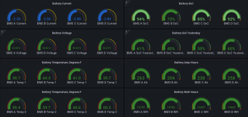
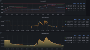

Top balancing was just redone on packs B & C. They should come back in line with the others after a couple of charge cycles. Keeping all of the packs together was a challenge until a fan was added to minimize the difference in temperature. They are stacked vertically in pairs and the ones near the floor were much cooler. The four BMS units also appear to vary a little from one to another. Plus, the BMS reports any current less than 0.5A (charge or discharge) as 0.0A which causes errors in the SoC measurement. When the system transitions to float the current bounces around near 0.5A until the PV output drops off.
Thanks again to you for some excellent work and @TheSmartGerman for the updated Chargery script!
This is great!The Pi Zeroes are pretty much unobtanium for a rational price. The OrangePi looks like a possible alternative but...
Those 4 bms readouts all in one look awesome.
I've been wanting to do the same for my 2x chargery and 2x JK BMS banks, all into one pi zero. Glad to see it can be done and thanks for doing the trial and error with the usb hubs!
Crashing scripts can be fixed easy enough thankfully.
Currently running into some SD card data corruption issues. Cleaned out my whole grafana history sadly.
shadowsteve
Solar Enthusiast
- Joined
- Feb 11, 2021
- Messages
- 265
I had card corruption issues after a while on a Pi4. I switched to using a SSD on my data collection system (Pi4 and ESP32's)This is great!
Those 4 bms readouts all in one look awesome.
I've been wanting to do the same for my 2x chargery and 2x JK BMS banks, all into one pi zero. Glad to see it can be done and thanks for doing the trial and error with the usb hubs!
Crashing scripts can be fixed easy enough thankfully.
Currently running into some SD card data corruption issues. Cleaned out my whole grafana history sadly.
OffGridICF
New Member
- Joined
- Aug 5, 2021
- Messages
- 41
Thanks, let me know if you want the scripts and Grafana json file and I'll try to figure out a simple way to pass them along.This is great!
Those 4 bms readouts all in one look awesome.
I've been wanting to do the same for my 2x chargery and 2x JK BMS banks, all into one pi zero. Glad to see it can be done and thanks for doing the trial and error with the usb hubs!
Crashing scripts can be fixed easy enough thankfully.
Currently running into some SD card data corruption issues. Cleaned out my whole grafana history sadly.
SD cards are not usually made with the highest quality NAND flash memory and lack the error correction circuitry included in SSDs. Like @shadowsteve , I'm booting off an SSD with no SD card. I'm also using a Pi 400, similar hardware to a Pi 4. I'm not sure if a Pi Zero will run 4 Python serial port capture scripts concurrently. A Pi Zero 2 might be a good option which I'd like to try if I could only get one...
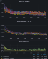
The Chargery BMS cell voltage measurements bounce around a good bit so I tried the Grafana averaging function to smooth it out. The code looks like this:
avg_over_time(BMS_A{mode="CellNum1"}[2m])
Using this function to average the cell delta voltage creates a small error in the result since it won't average the calculated delta voltage. The minimum and maximum cell voltages must be found from the averaged cell voltage and then subtracted like this:
1000 * (max(avg_over_time(BMS_A{mode=~"Cell.*"}[2m])) - min(avg_over_time(BMS_A{mode=~"Cell.*"}[2m])))
This tends to smooth the peaks in the cell voltage so the min/max may be a little lower than the actual peak values. It may make more sense to just accept that this measurement will be noisy. Here's an example comparing the results with and without averaging:
The noise on the cell voltages increases dramatically when the Chargery BMS enables passive balancing. The cell voltages also diverge quite a bit. The pack is charging at about 25A so it seems the 2A passive balancing should not move things around that much. It's set to balance at 3.37V/cell here:
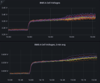
After it switches from charge to discharge the cell voltages converge again like in the first plot in this reply. It should be accurate enough for cell protection but it makes me wonder what is really going on.
BarkingSpider
Carbon Lifeform
Thanks for the idea of using averaging, this makes sense...
Similar threads
- Replies
- 3
- Views
- 166
- Replies
- 1
- Views
- 411
- Replies
- 17
- Views
- 400
- Replies
- 21
- Views
- 605
- Replies
- 14
- Views
- 395


