diy solar

diy solar

One battery out of 3 behaving different

Simi 60

New Member
Joined
Jul 10, 2021
Messages
159
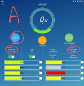
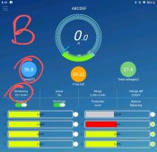
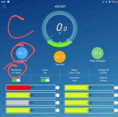
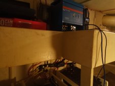
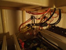
Have 3 seperate eve 280 24v batts installed.
All matched and batched
All top balanced
All cell terminals cleaned, noaloxed and torqued
All cables the same size.
2 batteries seem identical or near enough
But one (A) draws less when under load and has more go in when under charge and the imbalance at charge end is slightly higher than others.

Thoughts?
And anything to be to concerned about?

Add: screenshot taken while still plugged into shore power
Temps dropped a bit when unplugged.
 

Attachments

  • Screenshot_2022-01-13-20-05-03-301_1_1.jpeg
    Screenshot_2022-01-13-20-05-03-301_1_1.jpeg
    143.2 KB · Views: 19
  • Screenshot_2022-01-13-20-10-30-120_1.jpeg
    Screenshot_2022-01-13-20-10-30-120_1.jpeg
    151.6 KB · Views: 18
  • Screenshot_2022-01-13-20-08-06-660_1.jpeg
    Screenshot_2022-01-13-20-08-06-660_1.jpeg
    146 KB · Views: 18
Were all of the cells bought at once or via different orders or suppliers ?
Pack A appears to be less matched but NOT terribly out of whack.
Are these connected to a common DC BUS such as a 4 point BusBar ?
I found that even just doubling the Battery Lugs on a busbar can throw them off.
 
Thanks for the reply Steve,
All bought at same time from Amy
All matched and batched
All top balanced
All fully charged and let sit for a week to sort themselves out before install

"Steve said... Are these connected to a common DC BUS such as a 4 point BusBar ?
I found that even just doubling the Battery Lugs on a busbar can throw them off."

That's likely the culprit
Each battery has a 200amp mrbf
All + and - go to their own post with same length cable
From that post to 425amp fuse with a 4 inch cable.
 
Actually, my above comment isn't entirely correct
Seems + go to the shunt for a Victron 702 battery monitor
Negs seem to go to the 425amp shunt

I am not doing the wiring.
 

Attachments

  • IMG_20220114_075812_445.jpg
    IMG_20220114_075812_445.jpg
    160.4 KB · Views: 21
  • IMG_20220114_075738_412.jpg
    IMG_20220114_075738_412.jpg
    201.7 KB · Views: 21
I would suggest a change... A pair of these below with the batts connected to these. The shunt should only have 1 wire to & from it, it's not supposed to be used as a Junction. Keep in mind as well, that each MRBF and the shunt is a voltage drop & an amperage drop as well... not huge but depending on where it get's "stacked up" as such it can cause peculiar effects. During all of my testing and configuration modifications, these "little" things have popped up. Even 200A vs 300A MRBF have a different voltage drop..

250A-BusBars.JPG

 
Comparing cell voltages at near full charge with no load is pretty meaningless. You are showing cell voltages above 3.45v meaning it has not even been bled of it charging surface capacitance charge. Battery A seems to be more out of balance but without knowing discharge history it is difficult to make any definitive conclusion.

I assume from your BMS picts the three 8s battery stacks are individually stacked and paralleled as three separate 24v batteries so each BMS current represents current from its individual series string battery pack.

How to quickly check for cell matching or a bad cell. - Do a load test, as followed:

Run batteries down until highest rested cell voltage is below 3.40v and lowest rested cell voltage is above 3.30vdc. Rested means no load for at least about 5 minutes. When doing the discharging it would be a good time to take DVM and measure voltage drop across all your connections to check for excessive voltage drop indicating a poor connection. You should have at least 15-20 amps discharge rate on each string to show up any connection resistance problems. A cheap IR temp sensor gun is a quick way to check for terminal heating.

When you remove load the cells voltage will rise back up a bit over a two to three minute period. After three minutes they should pretty much settle to their equilibrium cell voltage. They all need to be within the 3.300v to 3.400v range after reaching equilibrium for the following load test to produce useful results. Remember no load voltage will rise a bit after load removed so keep load on until highest voltage cell drops to at least below 3.350v.

Take a picture of the three BMS's output at this initial rested no load state. It is okay the batteries don't start with same cell voltage, only that they are resting between 3.300v and 3.400v.

Apply load on inverter so it draws a total of 60 to 90 amps DC input current. Ideally each battery would take a third of current but that likely will not be the case.

Record initial current on each of three strings. At about two minutes into moderate load record the three string currents again. This will indicate load sharing balance between the three battery strings.

After about 3 minutes of load take a picture of each BMS as close in time as you can take the pictures. You can then remove load on inverter.

For each cell, subtract their respective cell voltage after the three minute load from the initial respective cell starting no load voltage.

If cells are truely matched the delta voltage slump of load to no-load cell voltage should all be close to the same voltage, at least for cells in the same series string subjected to same load current. For 20 to 30 amps for cell current, each should slump in terminal voltage no more than 50 to 100 mV for ambient temp of 15-28 degs C. String carrying more current should have the greatest cell terminal voltage slump. Lower ambient temp also increases terminal voltage slump with load current so don't run test below 15 degs C.

Within each cell series string, all cells in that particular string should be close to same matching voltage slump at 3 minutes since all cells in that string are being subjected to same load current. The greater the cell voltage slump the poorer the cell. It means it has higher internal impedance than other cells in the same series stack.

Given you have what you have, it is best to sort cells by their voltage slump for same load current and series stack cells with same voltage slump for same amount of test load current. This will give the best match for cells in series stack. It may increase the load sharing mismatch between parallel battery array strings but it is better to have cells in same series string have the best matching.
 
Last edited:
Battery A is to right in pic
It is closest to the posts, but all cable is same length.
I was wondering about the order that the cables were connected at the shunt. Hypothesizing that the cable connector furthest from the shunt surface made the poorest contact as it would have to pass thru the other 2 connectors (2 surfaces each).
 
I was wondering about the order that the cables were connected at the shunt. Hypothesizing that the cable connector furthest from the shunt surface made the poorest contact as it would have to pass thru the other 2 connectors (2 surfaces each).
Yeah, I find it hard to believe they could be that sensitive but wait.......now we have some new weird shite happening.
 
Weird shite.

Battery A app was showing no amps used under load and none during charge, just reading zero yet still balancing cells.
Blue light on BMS is off
Thought it might have done the 200 amp fuse but we have 27+ v at the terminals

Batt A and B were working perfectly

Now, several hours later batt A is still doing nothing on the app, but cells still balancing
AND........battery B app is now doing the battery A thing and no blue light on BMS.

Battery C app shows that it is now taking full load, cells perfectly balanced

Shot all terminals, nothing warmer than ambient temp.
 
Well, been running a few weeks now and appart from those initial teething problems it's been running great.
Trouble maker batts I pulled BMS wires out and reconnected and away she went
No changes made.

Boats on the hard in a shed getting mainenance so solar hasn't come into play yet but we charge batts with victron 5000/120 multiplus, turn off shore power when charge stops at 27.2v and we use everything onboard for about 3 X 12 hour cycles

Everything is :
240v 180 litre hot water system left on to boil when it likes (never done that with AGM)
240v refrigeration X 4 totalling 900 litres (usually run 3 but what the hell)
Electric kettle, toaster, microwave, pressure cooker usage
Vacuum cleaner
Multiple PC and large LED screens
24v lights, water pump, toilet usage.

Very impressed.
 
Back
Top