Adamk
New Member
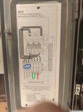
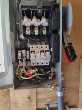
Hello, one of our inverters (sunpower SP-5200) that I haven't checked in a while is giving an error. The system is about 17 years old, I checked the manual and it is a low input voltage issue. I opened the DC Disconnect (SBCD 4-40) and started probing. There are 3 wires coming out of the solar panels (SPR-220) One of the wires has no voltage but the other 2 do. I have a second inverter in that system that has voltage on all 3 wires and is working fine.
What would be the next steps for troubleshooting? Does anyone recommend someone in Southern California that can come out and help diagnose and repair the issue at a reasonable cost?
End goal for that system is to disconnect from the grid add battery backup but will be posting soon on how to accomplish that