diy solar

diy solar

Optimum voltages for mppt?

ianganderton

Auckland, NZ
Joined
Nov 8, 2019
Messages
771
Location
Auckland, New Zealand
My current understanding has been to put solar panels in series to make the most of the efficiencies of higher voltages and lower amps

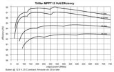
I’ve just come across this graph though that shows higher mppt efficiencies for lower voltages.
4F6B8B59-2404-41DC-B7F3-2D804027BF8A.jpeg

Are any efficiencies like this device specific? Is it swings and roundabouts cable efficiencies vs mppt efficiencies?
 
It appears that plot may be specific to something called a Tristar. I think it varies by controller and panel configuration and by the hour so I have not reached a conclusion one way or the other. I just put seven panels in series and let it do its thing.
 
Yes, it is device specific but usually a very similar looking graph. Some manufacturer's tweak things to move peak efficiencies around (inverters are another thing this is done) because that's where they believe most of their users are sitting.

Within the controller, cabling, PCB traces, inductor wire, inductor former material, transistors, it all adds up.
 
My current understanding has been to put solar panels in series to make the most of the efficiencies of higher voltages and lower amps

I’ve just come across this graph though that shows higher mppt efficiencies for lower voltages.

Are any efficiencies like this device specific? Is it swings and roundabouts cable efficiencies vs mppt efficiencies?

Like most things, the advice to maximize PV array voltage, is advice based on an oversimplified understanding that makes sense in some contexts but not all contexts.

As I understand it (and I'm about as far from an expert as they come--but I have done some research into this), Its a balancing act.

Maximizing PV array voltage (in an absolute sense, and relative to battery bank voltage):
  1. Maximizes wiring efficiency (minimizes voltage drop and line loss)
  2. Gives the MPPT sufficient margin to do its thing, particularly in less ideal conditions (I think)
  3. Is less shade tolerant(?) @gnubie considering bypass diodes, do you consider this point to be accurate, I've begun to question it lately?
  4. The higher the voltage differential between Varray and Vbatt the less efficient the DC-DC conversion will be (that is what the graph above shows)
Minimizing PV array voltage (relative to battery bank voltage):
  1. Maximizes MPPT DC-DC conversion efficiency
  2. Allows the possibility of parallel wiring for shade tolerance
  3. Does not maximize wiring efficiency
  4. Does not give the MPPT much margin to work with
So we have countervailing factors, moving in one direction will increase efficiency in some areas while reducing it in others.

What I have observed, is that (at least some) MPPT manufacturers (Victron, Epever) make a general reccomendation in the ballpark of 2.5:1 to 3:1 (Array Vmp to battery bank voltage) as the optimal balance. I.E. ~36vmp for a 12v battery, ~72vmp for a 24v battery.

I think what makes sense for your particular situation, depends on your particular situation. If you have a home or off grid cabin where wiring losses/wiring costs are you biggest consideration, and you have long wire runs, it probably makes sense to maximize voltage. This is sorta what I consider the default outlook/advice that you hear the most, but its not very applicable to those of us building a van or truck camper or small motorhome, where wire losses and wire lengths are minimal, system size is small. In those cases, it probably makes more sense to preference DC-DC conversion efficiency and shade tolerance as Vdrop is easy to virtually eliminate with properly sized short wire runs.


Please if you see anything that seems incorrect or partially correct point it out, I'm still learning.
 
What is likely happening on this plot is device is kicking in more parallel switching MOSFET's as current is higher.

At lower power it saves overhead consumption by reducing the number of MOSFET's it has to turn off and on. Since the current is low it does not need the low resistance of multiple parallel MOSFET's. Input gate control to MOSFET's is highly capacitive and driver takes power to chop the input capacitance between zero volts (OFF) and 10-12v (ON)

Generally the efficiency drops off at low power as overhead power to control the MOSFET input gates dominates. It peaks up in mid range then gradually drops at higher power due to MOSFET resistance and switching inductor losses.

Higher PV input voltage to battery voltage ratio usually has a bit less efficiency in power conversion because duty cycle of switching is shorter resulting in higher peak current through MOSFET's. This loss can be made up for with lower average current at the higher PV voltage input and lower loss in wiring from panel.

Some inverters also change the number of active MOSFET's to save overhead power at low output load levels.
 
Last edited:
  • Like
Reactions: Dzl
What is likely happening on this plot is device is kicking in more parallel switching MOSFET's as current is higher.

At lower power it saves overhead consumption by reducing the number of MOSFET's it has to turn off and on. Since the current is low it does not need the low resistance of multiple parallel MOSFET's. Input gate control to MOSFET's is highly capacitive and driver takes power to chop the input capacitance between zero volts (OFF) and 10-12v (ON)

Generally the efficiency drops off at low power as overhead power to control the MOSFET input gates dominates. It peaks up in mid range then gradually drops at higher power due to MOSFET resistance and switching inductor losses.

Higher PV input voltage to battery voltage ratio usually has a bit less efficiency in power conversion because duty cycle of switching is shorter resulting in higher peak current through MOSFET's. This loss can be made up for with lower average current at the higher PV voltage input and lower loss in wiring from panel.

Some inverters also change the number of active MOSFET's to save overhead power at low output load levels.
i see..so for 24v, pv input around 60-80 is good?
 
i see..so for 24v, pv input around 60-80 is good?

Here are a couple excerpts from charge controller manufacturers:

Outback Flexmax Manual:
"When designing the PV array, it is recommended for the Vmp to be approximately 12 to 24 volts higher than the nominal battery voltage for optimum performance. This will ensure that the Vmp is always above the battery voltage, which is required for charging. Higher voltages are not recommended, as they may reduce the FLEXmax conversion efficiency"

Victron Smartsolar Manual:
"Recommended number of cells for highest controller efficiency:144 cells (4x 12V panel or 2x 24V panel in series)."
 
Back
Top