diy solar

diy solar

Overkill BMS as primary low voltage disconnect

ggh

New Member
Joined
Oct 17, 2022
Messages
13
Hi all, I have a DIY small 12 volt solar system with a 1500 watt inverter, 4s 120 amp overkill BMS connected to 4 lifepo4 cells, and a renogy 40 amp charge controller. My inverter has a default low voltage disconnect of 9.5 volts that can’t be changed and that’s lower than I want. Can I use my overkill BMS as the main low voltage disconnect? If not, is there an easy and cost effective way to add a low voltage disconnect?

Thanks in advance!
Les say you want the LVD=low voltage disconnect to be 12 volts.
1500 ac watts / .85 conversion factor / 12 volts = 147.058823529 service amps
That is a brutal amount of current for the FETs=field effect transistors to try to disconnect.
The worst part of it is FETS can fail closed which means you won't be protected by your BMS and you won't know it until your battery is destroyed.

If the inverter is remote switchable or has a simple mechanical on/off switch you can control the inverter via a Victron battery protect.
Its usually cheaper and easier to get an inverter/charger that has a programmable low voltage disconnect.
 
Hi all, I have a DIY small 12 volt solar system with a 1500 watt inverter, 4s 120 amp overkill BMS connected to 4 lifepo4 cells, and a renogy 40 amp charge controller. My inverter has a default low voltage disconnect of 9.5 volts that can’t be changed and that’s lower than I want. Can I use my overkill BMS as the main low voltage disconnect? If not, is there an easy and cost effective way to add a low voltage disconnect?

Thanks in advance!
Your Overkill BMS will either disconnect by one of the cells going low or the group going low.
You can adjust the numbers how you like.
 
Les say you want the LVD=low voltage disconnect to be 12 volts.
1500 ac watts / .85 conversion factor / 12 volts = 147.058823529 service amps
That is a brutal amount of current for the FETs=field effect transistors to try to disconnect.
The worst part of it is FETS can fail closed which means you won't be protected by your BMS and you won't know it until your battery is destroyed.

If the inverter is remote switchable or has a simple mechanical on/off switch you can control the inverter via a Victron battery protect.
Its usually cheaper and easier to get an inverter/charger that has a programmable low voltage disconnect.
Could you explain this in layman’s terms? Are you saying that for the BMS components to disconnect for low voltage while a heavy load is connected will damage the BMS? And is there a cheaper way of creating a low voltage disconnect than the Victron? It seems like those are over $100.
 
Could you explain this in layman’s terms?
Maybe.
Are you saying that for the BMS components to disconnect for low voltage while a heavy load is connected will damage the BMS?
Yes.
And is there a cheaper way of creating a low voltage disconnect than the Victron? It seems like those are over $100.
Its a tricky problem.
You could use a BMS that uses a contactor(high current relay) but those have their own issues.
The premium for an inverter charger may actually be less than the price of the battery protect.
BTW the Vicrton battery protect can't be in the high current path of the inverter either.
That is why I suggest to have the battery protect control a solid state relay that in turn controls the power switch of the inverter.
 
Without damaging the system?
Lets slow down a min.
1st what batteries do you have? how many amp hour are they rated for?
2nd how many AC watts are you actually using at any given time thru that inverter?
3rd do you have a fuse or circuit break in the line going to the inverter? if so what is it rated?
The reason I ask is because at BMS is only rated for 120 amps.
1500 watts / 120 amps = 12.5 volts and that is not taking your inverter efficiency into account so you have other issues with that set up.
 
If you are constantly seeing a low voltage issue with the inverter, I would not count on the BMS as primary. I would look at getting a bigger battery pack, or to tide you over to get a bigger battery get something that will shut the inverter off.

If this is an issue of you want the battery shut off if you leave the inverter on for a few days, then since there's no load on the inverter, the BMS would be OK; however, I highly doubt this is the scenario.

Do you know why your inverter has such low voltage cutoff? Some inverters are designed to work with chemistries other than Lead or Lithium and have a very broad input range that reflect that. Nickel Iron batteries do this, but equipment designed to operate them are a bit harder to find.
 
Lets slow down a min.
1st what batteries do you have? how many amp hour are they rated for?
2nd how many AC watts are you actually using at any given time thru that inverter?
3rd do you have a fuse or circuit break in the line going to the inverter? if so what is it rated?
The reason I ask is because at BMS is only rated for 120 amps.
1500 watts / 120 amps = 12.5 volts and that is not taking your inverter efficiency into account so you have other issues with that set up.
I have 4 Catl 3.2 volt 300 ah cells. The most I use is about 1200 or 1300, and that’s only for minutes at a time. Typical load is a fridge freezer combo that pulls up to a few hundred watts. My circuit breaker is rated for 150 amps since the BMS won’t take as much as the inverter can draw without shutting down.
 
If you are constantly seeing a low voltage issue with the inverter, I would not count on the BMS as primary. I would look at getting a bigger battery pack, or to tide you over to get a bigger battery get something that will shut the inverter off.

If this is an issue of you want the battery shut off if you leave the inverter on for a few days, then since there's no load on the inverter, the BMS would be OK; however, I highly doubt this is the scenario.

Do you know why your inverter has such low voltage cutoff? Some inverters are designed to work with chemistries other than Lead or Lithium and have a very broad input range that reflect that. Nickel Iron batteries do this, but equipment designed to operate them are a bit harder to find.
I don’t see low voltage unless I leave an appliance running all night and the bms has shut the battery off from low voltage by morning. This usually happens with my deep freeze or my wood stove blower. I’m not sure why the inverter has that low of a voltage cutoff. It’s a Giandell 1500 watt psw.
 
Any suggestions for a long lasting 1500 watt inverter with a better low voltage disconnect?
 
Maybe.

Yes.

Its a tricky problem.
You could use a BMS that uses a contactor(high current relay) but those have their own issues.
The premium for an inverter charger may actually be less than the price of the battery protect.
BTW the Vicrton battery protect can't be in the high current path of the inverter either.
That is why I suggest to have the battery protect control a solid state relay that in turn controls the power switch of the inverter.
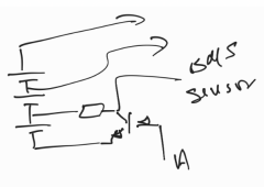
I have a similar problem. Among the ugly options that I'm considering is opening the battery and using a circuit to fool the BMS by disconnecting one cell and use the BMS as a "relay"...

1670371372234.png
 
I have a similar problem. Among the ugly options that I'm considering is opening the battery and using a circuit to fool the BMS by disconnecting one cell and use the BMS as a "relay"...

View attachment 123441

I can't really see your document but I get the idea.
Is the primary consideration financial?
Not necessarily...
The idea is simple. The BMS sensor has to have a high impedance, so I can connect any resistance in series, and using an optocoupler, a transistor-like above, or anything I can simulate one cell loss power and use the BMS as a relay. After that its hysteresis will maintain the inverter off until the battery is charged.
I don't understand why manufacturers do not allow to adjust these voltages.
Neither the Inverter nor the BMS/Battery manufacturers... It is not difficult or expensive for them and adds value to their product.
 
I don't understand why manufacturers do not allow to adjust these voltages.
Mine does.
Most of the smart ones do.

The problem is destroying the FETS using a BMS as a means of disconnect under significant load.

Am I misunderstanding you?
 
Mine does.
Most of the smart ones do.
This is easy to accomplish... All inverters should have that... I have seen many with LVD 9.5 V, not for LiFEPO4, not for any battery...
The problem is destroying the FETS using a BMS as a means of disconnect under significant load.

Am I misunderstanding you?
Yes... That worries me too... Both sides... the BMS and the inverter MOSFETs... I was considering adding a high-capacity capacitor for the inverter...
But anyway... Are not they -by design- (the BMS and the Inverter) capable of handling this?

The inverter is cheaper... Around 150 USD. I prefer to play w/ it... I'm considering hacking its circuit too...
 
I'm considering is opening the battery and using a circuit to fool the BMS by disconnecting one cell and use the BMS as a "relay"...
This is kind of what @Bud Martin was suggesting in the other thread but opening the inverter and bypassing the physical on/off switch and turning the inverter on/off with a voltage sensing controller and probably a relay of sorts.

Looks like he's done it successfully. I'd say if you're comfortable opening a battery and cutting off a BMS cell wire, you're at least equally qualified to bypass an on/off switch.

All this without messing with your battery and its internal safety mechanism.
 
Beside the issue of using BMS as disconnect, when you turn the BMS back on you will have high inrush current when the capacitor banks in the inverter are being charged up, surge may be high enough to trip BMS over current sensing unless you implement pre-charge circuit too.
 
This is kind of what @Bud Martin was suggesting in the other thread but opening the inverter and bypassing the physical on/off switch and turning the inverter on/off with a voltage sensing controller and probably a relay of sorts.

Looks like he's done it successfully. I'd say if you're comfortable opening a battery and cutting off a BMS cell wire, you're at least equally qualified to bypass an on/off switch.

All this without messing with your battery and its internal safety mechanism.
It is not an on-off switch but a push button that toggles the inverter on-off. It sold to a multilayer PCB
My other option is to use a relay or an optocoupler, or just a high-pass RC filter to send a pulse to the correct push-button terminal that turns off the inverter.
 
Back
Top